Tandy 1000
inter
8237
A/8237
A-4/fl?37
A-5
Technical Reference Manual
Mask Register - Each channel has associated
with
It a
mask
bit
which can be set to disable the incoming
DREQ. Each mask
bit
is set when
its
associated channel
produces
an
EOP
if
the channel
is
not programmed for
Autoinitialize. Each
bit
of
the 4-blt Mask register may
also
be set
or
cleared separately under software control.
The entire register is also set by a Reset. This disables
ali DMA requests until a clear
Mask register
instruction
allows them to occur. The instruction to separately set
or
clear the mask bits is similar in form to that used with
the Request register.
See
Figure 5 for instruction
ad-
dressing.
1 , 5 4 3 2 I 0 _
Bit
Number
l I
1.1
I
II
IL{l
II
00
~OO,,""""O~.,,"
Don't Care
01
Select
Channa.
I 1
mask
bit
10 Select channel 2
mask
bit
11
Select channel 3
mask
bit
o Clear
mask
bit
1 Set mask
bit
All four bits
of
the Mask register may also be
written
with
a single command.
Clear channel 0 mask
bit
Set channel 0
mask
bit
Clear channel 1 mask
bit
Set channel 1 mask bit
Clear channel 2 mask bit
Set channel 2 mask
bit
Clear channel 3
mask
bit
Sel cnannel 3
mask
bit
Operation
Slg""la
Reglater
CS
lOR
lOW
A3
A2
Al
AO
Command
Write
0
1
0 1 0
0
0
Mode
Write
0
,
0
1 0 1 1
Request
Write 0
1 0 1 0 0
1
Mask. Set/Reset 0
1
0
,
0
1 0
Mask
Write
0
1 0
,
1
1
,
Temporary
Read
0 0 1 1
1 0 1
Status Read 0 0 1
,
0 0
0
Figure
5.
Definition
of
Register Codes
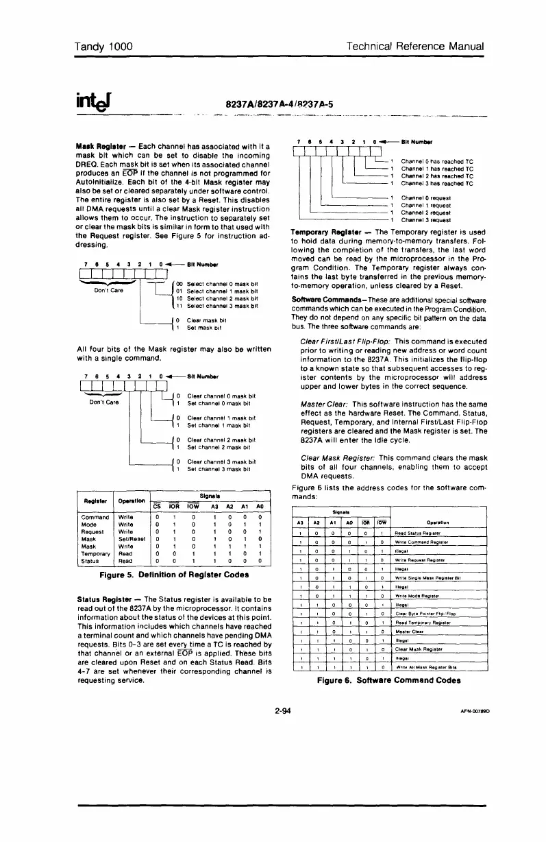
Status Register -
The
Status register is available to be
read out
of
the 8237A by the microprocessor. It contains
information about the status
01
the devices at
this
point.
This information includes which channels have reached
a terminal
count
and which channels have pending DMA
requests. Bits
0-3
are set every
time
a
TC
is reached by
that channel or
an
external EOP Is applied. These bits
are cleared upon Reset and on each Status Read.
Bits
4-7
are set whenever their corresponding channel is
requesting service.
1 , 5 4 3 2 I 0
__
BII
Number
IE
,Channel
OMs
reached
TC
, Channel 1 has reached TC
1 Channel 2 has reached TC
,
Channel 3 has reached
TC
1 Channel 0 request
, Channel 1 request
1 Channel 2
reQuest
1 Channel 3 request
Temporary Register - The Temporary register
is
used
to hold data
during
memory-to·memory transfers. Fol-
lowing the
completion
of
the transfers, the last word
moved can
be
read by the microprocessor in the Pro-
gram
Condition.
The Temporary register always con·
tains the last
byte
transferred
in
the previous memory-
to·memory operation, unless cleared by a Reset.
Soflwere
Commands-
These
are
additional special software
commands which
can
be
executed
in
the
Program
Condition.
They
do not depend
on
any specific bit pattern
on
the
data
bus.
The
three software commands
are:
Clear
Firsf/Last
Flip-Flop: This command is executed
prior to
writing
or reading new address or word count
information
to
the 8237A. This initializes the f1ip·f1op
to
a known
state
so that subsequent accesses to reg-
ister
contents
by the microprocessor will address
upper and
lower
bytes in the correct sequence.
Mas fer Clear: This software instruction has the same
effect as the hardware Reset. The Command. Status,
Request, Temporary, and Internal First/Last Flip-FlOp
registers are cleared and the Mask register is set. The
8237A will
enter
the Idle cycle.
Clear Mask Register: This command clears the mask
bits
of
all
four
channels, enabling them to accept
DMA requests.
Figure 6
lists
the
address codes for the software com-
mands:
Read
StatuI
Register
Write
Commend
Reoister
Illegal
Write ReQultsl
Register
Illegal
Write
Single
Mask
Regia'arBil
Illegal
Writa
Moda
Register
Illegal
CleafBytePoinlerFlip/FIOp
Ra.d
Temporary
Regiatar
Illegal
Clear
Mask
Register
Illegal
Nrltt!
All
Mask
Regiater
Bits
Figure 6. Software Command Codes
2-94
AFN·OO789D
 Loading...


