Tandy 1000
Technical Reference Manual
8237A/8237~4/8237~5
Controller enable
Controller
disable
DREQ sense actlye high
DREQ
sense acllye low
Fixed priority
Rolatlng priority
Address
Increment select
Address decrement select
Autoinitialization dlsabla
Autolnillalization
anable
Late write selection
Extsnded
wrlle
eelectlon
If bit
3=
1
Normal timing
Compressed tim
I"
If
bit
0=
1
Memory·tOomemory
dluble
Memory.tOomemory enable
DACK sense actiYe
low
DACK sense actiYe high
Channel 0 address hold
dluble
Channel 0 address hold enellle
If bit
0=0
q
00 Channel 0 select
01
Channel I selecl
10
Channel 2 select
1I Channel 3 select
00 Verify trsnsfer
01
Write trans'er
10
Reed
trsns'er
11
Illegal
XX
If bits 6 and
7=
11
Current Word Register - Each channel has a 16·bit Cur·
rent Word Count register. This register determines the
number
of
transfers to be performed. The actual number
of
transfers will
be
one more than the number pro·
grammed in the Current Word Count register (I.e., pro·
gramming a count
of
100
will result in
101
transfers). The
word
count
is decremented
aller
each transfer. The
intermediate value
of
the word
count
is
stored in the reg·
ister
during
the transfer. When the value in the register
goes from zero to FFFFH, a
TC
will
be
generated. This
register is loaded or read
in
successive
8·bit
bytes by
the microprocessor in the Program Condition. Follow·
ing the end
of
a DMA service it may also be reinitialized
by
an
Autoinitialization back to
its
original value. Auto·
initialize'can occur only when
an
EOP occurs. II
it
is not
Autoinitialized, this register will have a count
of
FFFFH
after TC.
Base Address and Base Word Count Registers - Each
channel has a pair
of
Base Address and Base Word
Count registers. These 16·bit registers store the original
value
of
their associated current registers. During Auto·
initialize these values are used
to
restore the current
registers
to
their original values. The base registers are
written simultaneously
with
their corresponding current
register in B·bit bytes in the
P-fogram Condition by the
microprocessor. These registers cannot
be
read by the
microprocessor.
current
Address Register - Each channel has a 16-bit
Current Address register. This register holds the value
of
the address used during DMA transfers. The address
is automatically incremented
or
decremented after each
transfer and the intermediate values
of
the address are
stored in the Current Address register during the trans·
fer. This register is written
or
read by the micro-
processor in successive 8·bit bytes.
It may also be reini·
tialized by
an
Autoinitialize back to
its
original value.
Autoinitialize takes place only after
an
EOP.
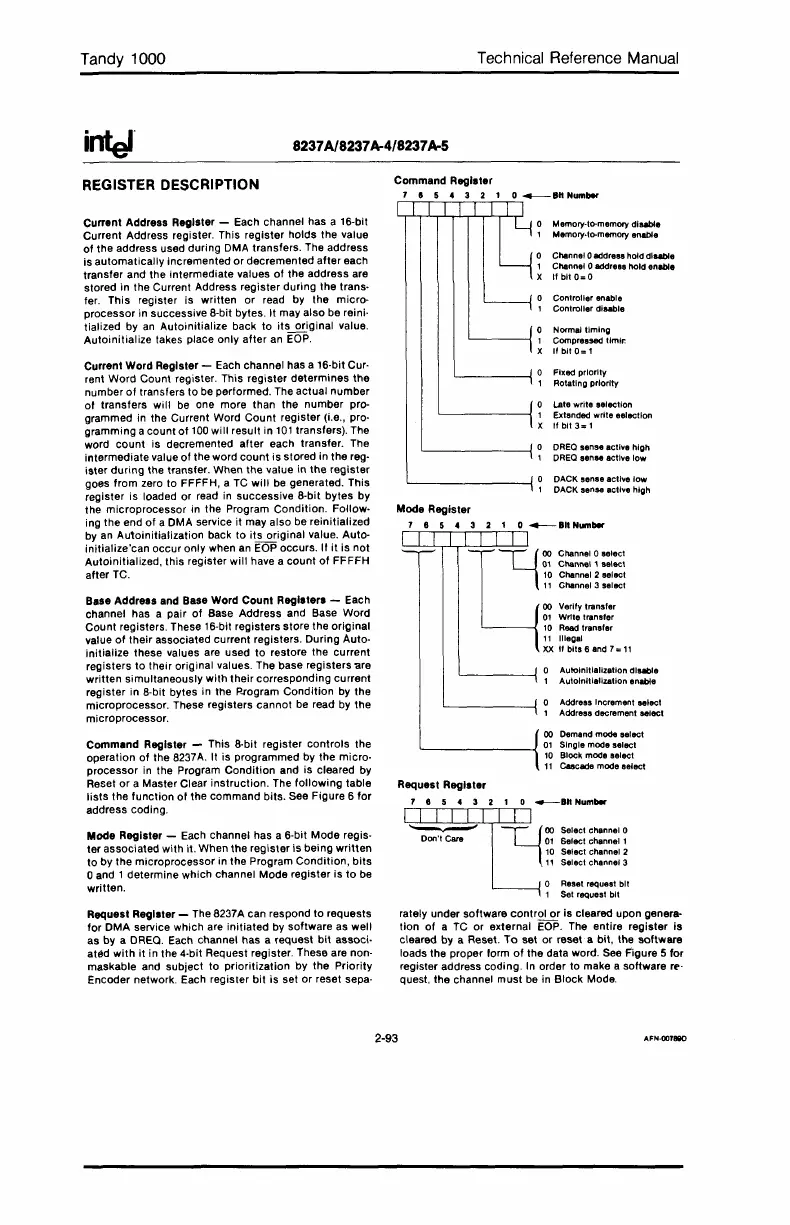
REGISTER DESCRIPTION
Command Register - This 8·bit register controls the
operation
of
the
B237A.
It
is
programmed by the micro·
processor
in
the Program
Condition
and is cleared by
Reset
or
a Master Clear instruction. The
following
table
lists
the function
of
the command bits. See Figure 6 for
address coding.
Mode Register - Each channel has a 6·bit Mode regis·
ter associated with it. When the register
is
being
written
to by the microprocessor in the Program Condition,
bits
oand 1 determine which channel Mode register
is
to
be
written.
00 Demand mode select
L---------l
01
Singia mooa select
10
Block mooa salect
11
C8acade mooa salecl
Request Register
7 8 5 4 3 2 1 0
_8"
Numbar
l-UllII~1
II"'_"M"~"
Don't Care
01
Select channal 1
10
Selact channal 2
11
Selact channel 3
o Reset request bit
1 Set requast bit
Request Register - The 8237A can respond to requests
for DMA service which are initiated by software as well
as by a DREQ. Each channel has a request
bit
associ·
atEld
with
it
in the 4·bit Request register. These are non·
maskable and subject to prioritization by the Priority
Encoder network. Each register
bit
is set or reset sepa·
rately under software control
or
is cleared upon genera-
tion
of
a
TC
or external
EOP.
The entire register Is
cleared by a Reset.
To
set or reset a bit, the software
loads the proper form
of
the data word.
See
F'igure 5 for
register address coding.
In
order to make a software r('·
Quest,
the channel must
be
in Block Mode.
2-93
AFN·OOT88D
 Loading...


