Tandy 1000
Technical Reference Manual
8237AJ8237~4/8237~5
TRANSFER TYPES
Each
of
the
three active transfer modes can perform three
different types of transfers.
These
are
Read,
Write
and
Verity.
Write
transfers
move
data
from
and
1/0 device to
the
memory
by activating
~
and
fOR.
Read
transfers
move
data
from
memory
to
an
1/0 device by activating
MEMR
and
00.
Verity
transfers are pseudo transfers.
T/1e
8237A operates
as
in
Read
or
Write
transfers generating addresses, and responding
to
EOP,
etc.
However,
the memory
and
1/0 control lines
all
remain inactive.
The
ready input
is
ignored
in
verity
mode.
which fixes
the
channels
in
priority order based upon the
descending
value
of their number.
The
channel
with
the lowest
priority
is
3 followed by
2,
1
and
the highest priority channel,
O.
After
the recognition of
anyone
channel tor service,
the
other channels are prevented
from
interferring
with
that ser-
vice until
it
is completed.
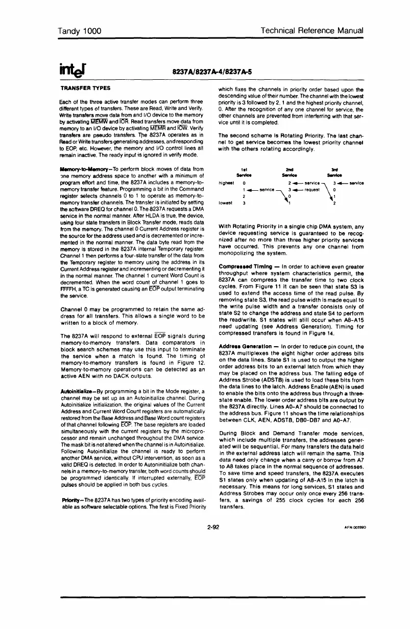
The second
scheme
Is Rotating Priority. The last chan-
nel to get service becomes the lowest priority channel
with
the others rotating accordingly.
With Rotating
Priority
in a single chip DMA system, any
device requesting service is guaranteed to be recog-
nized after no
more
than three higher priority services
have occurred. This prevents
anyone
channel from
monopolizing
the
system.
Compre
..
ed
TimIng
- In order to achieve even greater
throughput where system characteristics permit, the
8237A can compress the transfer time to
two
clock
cycles. From
Figure
11
it
can be seen that state 53 Is
used to extend the access time of the read pulse. By
removing state 53, the read pulse width is made equal
to
the write pulse
width
and a transfer consists only
of
state 52 to change the address and state 54 to perform
the read/write.
51
states will still occur when A8-A15
need updating (see Address Generation). Timing for
compressed transfers is found in Figure
14.
During Block and Demand Transfer mode services,
which include
multiple
transfers, the addresses gener-
ated will
be
sequential. For many transfers the data held
in the external address latch will remain the same. This
data need only change when a carry or borrow from
A7
to
A8 takes place in the normal sequence
of
addresses.
To
save
time
and speed transfers, the 8237A executes
51
states only when updating
of
A8-A15
in
the latch
is
necessary. This means for long services,
51
states and
Address Strobes may
occur
only once every
256
trans-
fers, a savings
of
255 clock cycles for each
256
transfers.
Addre
..
Generation - In order to reduce pin count, the
8237A mUltiplexes the eight higher order address bits
on the data lines. State
51
is used to output the higher
order address
bits
to an external latch from which they
may
be
placed on the address bus.
The
falling edge
of
Address Strobe (ADSTB)
is
used to load these
bits
from
the data lines
to
the latch. Address Enable (AEN)
is
used
to
enable the
bits
onto the address bus through a three-
state enable. The lower order address bits are output by
the 8237A directly. Lines AO-A7 should
be
connected to
the address bus. Figure
11
shows the time relationships
between
ClK,
AEN, ADSTB, DBO-DB7 and AO-A7.
3nI
SenIce
2nd
SenIce
o 2_
.ervice
\3
_service
1
......--
service'\.
3....-
request 0
2
,0
1
3 1 2
I
••
Sentce
highest
lowest
PrIority-
The
8237A
has
two
types of priority encoding avail-
able as software selectable options.
The
first
is
Fixed
Priority
Channel 0 may be programmed to retain the same
ad-
dress for all transfers. This allows a single word to
be
written to a block
of
memory.
The 8237A will respond to external
EOP
signals during
memory-to-memory transfers. Data comparators
in
block search schemes may use
this
input to terminate
the service when a match
is
found. The timing
01
memory-to-memory transfers is found
in
Figure
12.
Memory-te-memory operations can
be
detected as
an
active AEN
with
no DACK outputs.
Auloinitialize-By programming a bit
in
the
Mode
register, a
channel
may
be
set
up
as
an
Autoinitialize channel. During
Autoinitialize initialization,
the
original values
of
the
Current
Address and Current
Word
Count registers
are
automatically
restored
from
the
Base
Address
and
Base
Word
count registers
of that channel following
Em'.
The
base
registers
are
loaded
simultaneously
with
the
current registers by
the
micropro-
cessor and remain unchanged throughout
the
DMA
service
The
mask
bit
is
not altered
when
the
channel
is
in
Autoinitialize.
Following Autoinitialize
the
channel
is
ready
to
perform
another
DMA
service, without
CPU
intervention,
as
soon
as
a
valid
DREQ
is
detected.
In
order
to
Autoninitialize both chan-
nels
in
a memory-to-memory
transler,
both
word
counts should
be
programmed identically. If interrupted externally,
EOP
pulses should
be
applied
in
both
bus cycles
Memory-to-Memory-
To
perform block
moves
of data
from
,ne
memory address space to another
with
a minimum of
program effort and
time,
the
8237A includes a memory-to-
memory transfer
feature.
Programming a bit
in
the
Command
register selects channels 0
to
1
to
operate
as
memory-to-
memory transfer channels.
The
transfer
is
initiated by setting
the
software
DREQ
for channel
O.
The
8237A requests a
DMA
service
in
the normal
manner.
After
HlDA
is
true,
the
device,
using four
state
transfers
in
Block
Transfer
mode,
reads
data
from
the
memory.
The
channel 0 Current Address register
is
the
source for the address used and
is
decremented or incre-
mented
in
the normal
manner.
The
data
byte
read
from
the
memory
is
stored
in
the
8237A internal
Temporary
register.
Channell then performs a four-state transfer of
the
data
from
the
Temporary register
to
memory using
the
address
in
its
Current Address register
and
incrementing ordecrementing
it
in
the normal
manner.
The
channell
current
Word
Count
is
decremented.
When
the
word count of channel 1 goes
to
FFFFH,
a
TC
is generated causing
an
BJP
output terminating
the
service.
2-92
AFN-00789D
 Loading...


