Tandy 1000
inter
823~
A/8237A-4/8237
A-S
Technical Reference Manual
and the last
four
states (521, 522, 523, 524)
for
the write-
to-memory half
of
the transfer.
IDLE CYCLE
When no channel Is requesting
service, the 8237A
will
enter the Idle cycle and perform "51" states. In
this
cycle the 8237A
will
sample the DREO lines every
clock
cycle to determine
if
any channel
is
requesting a DMA
service. The device
will
also sample
CS,
looking
for
an
attempt by the microprocessor
to
write
or
read
the
Inter-
nal registers
of
the 8237A. When
CS
Is low and HLDA Is
low, the 8237A enters the Program Condition. The
CPU
can now establish, change
or
Inspect the Internal
deflnl·
tion
of
the part by reading from
or
writing
to
the Internal
registers. Address lines AO-A3 are inputs
to
the device
and select which registers will
be
read
or
written. The
lOR and lOW lines are used
to
select and
time
reads
or
writes. Due to the number and size
of
the Internal regis-
ters,
an
Internal flip-flOp Is used
to
generate an addi-
tional
bit
of
address. This
bit
Is used
to
determine the
upper or lower byte
of
the 16-blt Address and Word
Count registers. The flip-flop Is reset by Master Clear
or
Reset. A separate software command can
also
reset
this
flip-flop.
Special software commands can be executed by the
8237A in the Program Condition.
Thes~ommands
are
decoded as sets
of
addresses
with
the
CS
and lOW. The
commands
do
not make use
of
the data bus. Instruc-
tions Include Clear First/Last Flip-FLop and Master
Clear.
ACTIVE CYCLE
When the 8237A
is
In
the Idle cycle and a non-masked
channel requests a DMA service, the device
will
output
an
HRO
to the microprocessor and enter the Active cy-
cle. It is in
this
cycle that the DMA service
will
take
place, in one
of
four modes:
Single
Tren,fer
Mode - In Single Transfer mode the
device
is
programmed
to
make one transfer only. The
word count
will
be decremented and the address dec·
remented or incremented following each transfer. When
the word count
"rolls
over" from zero to FFFFH, a
Ter-
minal Count
(TC)
will cause
an
Autoinitialize
if
the chan-
nel has been programmed to
do
so.
DR
EO
must
be held active
until
DACK becomes active in
order to
be
recognized.
If
DREO
is
held active through-
out the single transfer, HRO will
go
Inactive and release
the bus to the system. It will again
go
active and, upon
receipt
of
a new HLDA, another single transfer
will
be
performed, in 8080A, 8085AH, 8088, or 8086 system this
will
ensure one full machine cycle execution between
DMA transfers. Details
of
timing between the 8237A and
other bus control protocols will depend upon the char-
acteristics
of
the microprocessor involved.
Block
Tren,fer
Mode - In Block Transfer mode the
device Is activated by
DREO
to continue making trans-
fers during the service
until
a TC, caused by word
count
going to FFFFH, or
an
external End
of
Process
(EOP)
is
encountered. DREO need only
be
held active
until
DACK
becomes active. Again,
an
Autoinitialization will
occur
at the end
of
the service If the channel has been pro-
gremmed
for
It.
Demand
Tren,fer
Mode
-
In
Demand Transfer mode
the
device Is programmed
to
continue making transfers
until
a
TC
or
external EOP Is encountered or until DREO
goes Inactive. Thus transfers may continue
until
the
110
device has exhausted Its data capeclty. After the
110
device has had a chance
to
catch up, the DMA service Is
re-establlshed by means
-of
a DREO. During the
time
between services when the microprocessor Is allowed
to
operate, the Intermediate values
of
address and word
count
are stored in the 8237A Current Address and Cur-
rent Word Count registers. Only
an
EOP
can cause an
Autoinitialize at the
end
of
the service. EOP Is generated
either
by
TC
or by
an
external signal.
CascadeMocIe-This mode isused tocascade
more
than one
8237A together for simple
system
expansion.
The
HRO
and
HLDA
signals
from
the additional 8237A
are
connected
to
the
DR
EO
and
DACK
signals of a channel of
the
initial 8237
A.
This allows the
DMA
requests of the additional device to
propagate through
the
priority network circuitryof
the
preced-
ing device.
The
priority chain is preserved and
the
new
device
must
wait
for its turn to acknowledge requests. Since the
cascade channel of
the
initial 8237A
is
used only
for
prior-
itizing
the
additional device, it does not output
any
address
or control signals
of
its
own.
These could conflict with the
outputs olthe active channel
in
the
added
device.
The
8237A
will respond to
DREO
and
DACK
but
all
other outputs except
HRO
will
be
disabled. The ready input is ignored.
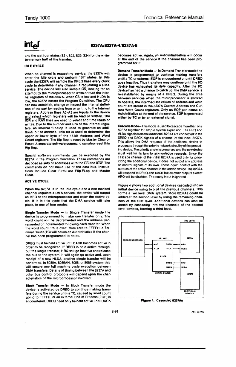
Figure 4 shows
two
additional devices cascaded
Into
an
initial
device using
two
of
the previous channels. This
forms a two level DMA system. More 8237As could be
added
at
the second level
by
using the remaining chan-
nels
of
the
first
level. Additional devices can also be
added by cascading
into
the channels
of
the second
level deVices, forming a third level.
1231A
f---
HRO
DREO
1-
I-l~a
~
HlDA
DACI<:
~
HLOA
1231A
DREQ
I---
HRO
DACI(~
HLOA
1231A
ADDITIONAL
DE'V)U:S
FIgure 4. Ce,ceded 8237A.
2-91
AFN·Q0789D
 Loading...


