Tandy 1000
inter
8237A/8237~4/8237A-5
Technical Reference Manual
APPLICATION INFORMATION
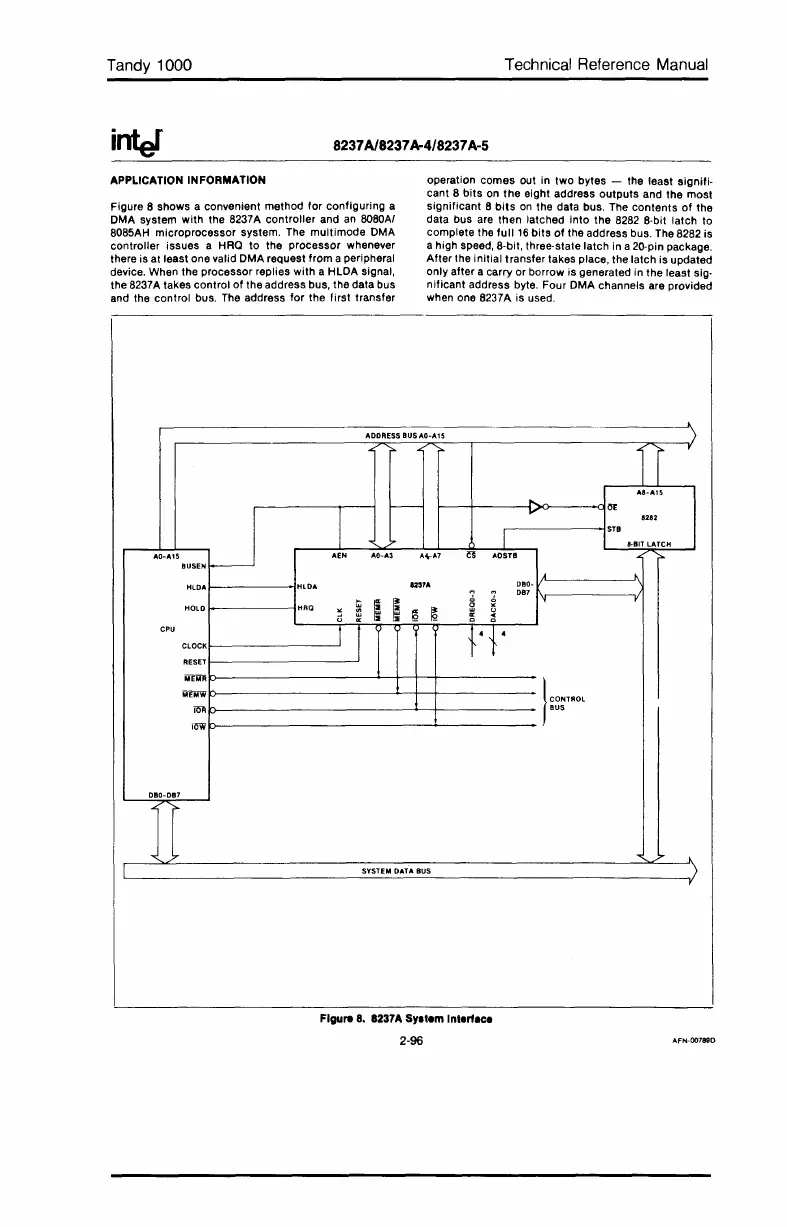
Figure 8 shows a convenient method for configuring a
DMA system
with
the 8237A controller and
an
8080AI
8085AH microprocessor system. The
multimode
DMA
controller issues a HRO
to
the processor whenever
there is at least one valid DMA request from a peripheral
device. When the processor replies
with
a HLDA signal,
the 8237A takes control
of
the address bus, the data bus
and the control bus. The address for the first transfer
operation
comes
out in two bytes - the least signifi-
cant 8
bits
on
the
eight address
outputs
and the most
significant 8
bits
on
the data bus. The contents
of
the
data bus are
then
latched into the 8282 8-bit latch to
complete the
full
16
bits
of
the address bus. The 8282 is
a high speed, 8-bit, three-state latch in a 20-pin package.
After the initial transfer takes place, the latch is updated
only after a carry or borrow is generated in the least sig-
nificant address byte. Four DMA channels are provided
when one 8237A is used.
ADDRESS
BUSAO-A15
)
~
".
r
"8-A15
r--
.....
M
I
....
8282
I
STB
7
8·BIT LATCH
AO-A15
AEN
AO-"3
A~A7
~
AOSTB
".
HUSEN
I---
j.
HLDA
HlDA
1231A
OBO-
DB7
HOLD
HRQ
Ii
I~
~
,
P-
~
()
()
'"
..
CPU
1 I
+4{4
CLOCK
RESET
MEMR
MEMW
l'~""
iOR
BUS
row
DBO-DB7
""
...
"<
....
>--
SYSTEM
DATA
BUS
)
,
Figure 8. 8237A
5y.'em
In'ertece
2-96
AFN-00789D
 Loading...


