Tandy 1000
Technical Reference Manual
inter
8272A
the Data Bus.
For
example,
if
the processor
cannot
handle Interrupts fast enough (every
13
I'S for MFM
mode) then
it
may poll the Main
Status
Register and
then bit
07
(ROM)
functions
just
like the Interrupt
signal.
If
a
Write
Command is in process, then the WR
signal
performs
the reset to
the
Interrupt signal.
The 8272A aiways operates in a multi-sector
transfer
mode. It
continues
to
transfer
data
until
the
TC
input
is
active. In Non-DMA Mode, the system
must
supply
the
TC
input.
If the 8272A is in the DMA Mode, no
Interrupts
are gener-
ated
during
the Execution Phase. The 8272A generates
DRO's (DMA Requests) when each byte
of
data is
available. The DMA
Controller
responds
to
this
request
with
both
a DACK =0 (DMA Acknowledge) and a
RD
=0
(Read signal). When the DMA
Acknowledge
signal goes
low
(DACK =
0)
then the DMA Request is reset (DRO =
0).
If
a
Write
Command has been programmed then a WR
signal
will
appear instead
of
RD.
After
the Execution
Phase has been
completed
(Terminal
Count
has
occurred) then an Interrupt
will
occur
(INT =
1).
This
signifies
the
beginning
of
the Result Phase. When the
first byte
of
data is read
during
the Result Phase, the In-
terrupt
is
automatically
reset (INT =
0).
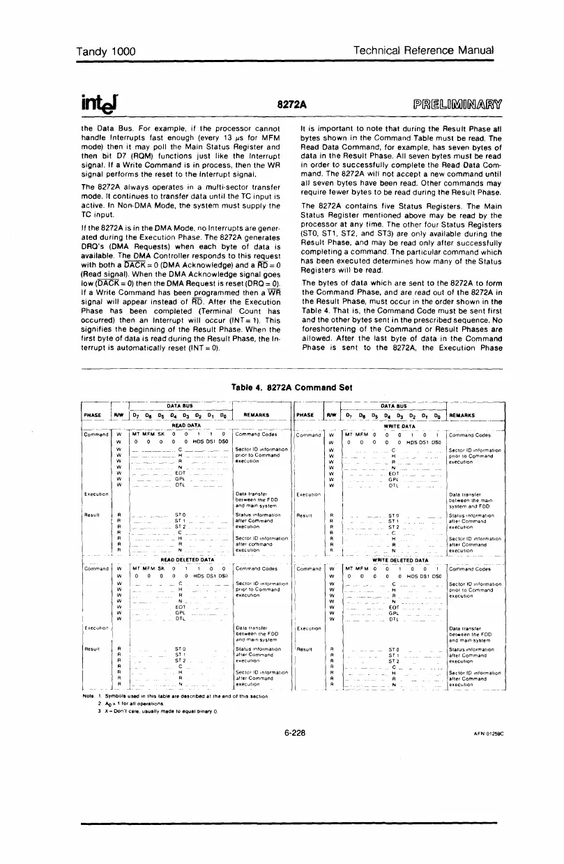
It
is
important
to
note
that
during the Result Phase all
bytes
shown
in
the Command Table
must
be read. The
Read Data
Command,
for
example, has seven bytes
of
data
in
the
Result
Phase. All seven bytes
must
be read
in
order
to
successfUlly
complete
the Read Data Com-
mand. The 8272A wili not accept a new
command
until
all
seven
bytes
have been read. Other
commands
may
require fewer
bytes
to
be read during the
Result
Phase.
The 8272A
contains
five
Status
Registers. The
Main
Status
Register
mentioned
above may be read by the
processor
at
any
time. The other four
Status
Registers
(STO,
ST1, ST2, and ST3) are
only
available during the
Result
Phase, and may be read
only
after
successfully
completing
a
command.
The particular
command
which
has been
executed
determines
how many
of
the
Status
Registers
will
be
read.
The bytes
of
data
which
are sent
to
the 8272A
to
form
the
Command
Phase, and are read out
of
the
8272A in
the
Result Phase,
must
occur
in the order shown in the
Table
4.
That is, the
Command
Code must be sent
first
and the
other
bytes
sent
in
the prescribed sequence. No
foreshortening
of
the
Command
or Result Phases are
allowed.
After
the
last byte
of
data
in the Command
Phase is sent
to
the 8272A, the
Execution
Phase
Table
4.
8272A Command Set
Data
transfer
bet
.....
een
the
Foo
and
main·
system
S,,'us
"'Nm",on
1
after
Command
execulion
sector.ro
Info.,.m...
'.tio
..
n
..
afler
Command
execullon
Sector
10
information
atlerCommand
execution
Data
transfer
bet
.....
een
the
main
system
and
FDD
Stalus
Intormatlon
alter
Command
execution
STD
ST,
ST
2
C.
H
A
N
STO
ST'
ST2
. C
H
A
N
!_AIT!
~~lET~D
D"T~
w
MFM
0 0 1 0 0 1
WOO
0 a a
Hos
DSl
oSO
W C _
Sector
to
Information
W H
prior
10
Command
W _ R
execution
W N
W
EaT
W
GPl
W
OIL
I
I
!
IbOCU"O"
IAesull
i
f
;cP'~'0"'m·'~mEa-··n·'dL:'_'·~'-'7
..
-."O'~'8-".
-~
-O~;:r-i-BUS-
---
---=r
-----------
__
1
~~__
_
?~~~_~
~~_~~
__
~~_l
~~~~K~
__
.
WAITE
OATA
WOO
1 0 1
wOO
HPSDSl
DSO
W C
Sector
10
mlormation
~
~
~:~~ul~o~ommand
W N
W EDT
W
GPl
W OTL
Sector
10
Information
allerCommand
execution
ST
0
ST,
ST2
C
H
A
N
Data
transler
bel
.....
een
ttle
FDD
and
main-system
STO
Slatus
Information
ST
1
allerCommand
ST 2
executiOn
C
H
Sec
lor
10
Information
R
alter
commClnd
N
execulion
a 1 1 a a
Command
Codes
a a
HDs
OS1
DSO
C
Sector
10
Information
H priOr
10
Command
R
execution
N •
EDT
GPl
oTl
W
W
W
W
W
W
W
W
W
Command
W
W
W
W
W
W
W
W
W
--iT-'
-~DATABU5"'-"-
---._--
PH"~
LRIW
...lOr..
ll!1l5~_~Ol-"D...L
•..
_R.E
..
M."_R.KS
......
_
READ DATA
------
---
--._-,-
--
---
MT
MFM
5K
0 0 , 1 0 CommClnd
Codes
o 0 0 0 0
HDS
OSl
DSO
C _
Sec
lor
10
Information
H
prior
to
Command
R exeCullOn
N .
EDT
GPl
oTl
I
Execution
I
IAesult
l-.
I"""
I!
1.
Symbols
used
in
this
table
are
de5cribed
at
the
end
0'
thiS
section
2_
Ao=
1
lor
all
operations
3 X = OOn', care,
usually
made
to
equal
Dinary
0
6-228
AFN-01259C
 Loading...


