Tandy 1000
TYPE
SN76494.
SN76496
PROGRAMMABLE
TONE/NOISE
GENERATOR
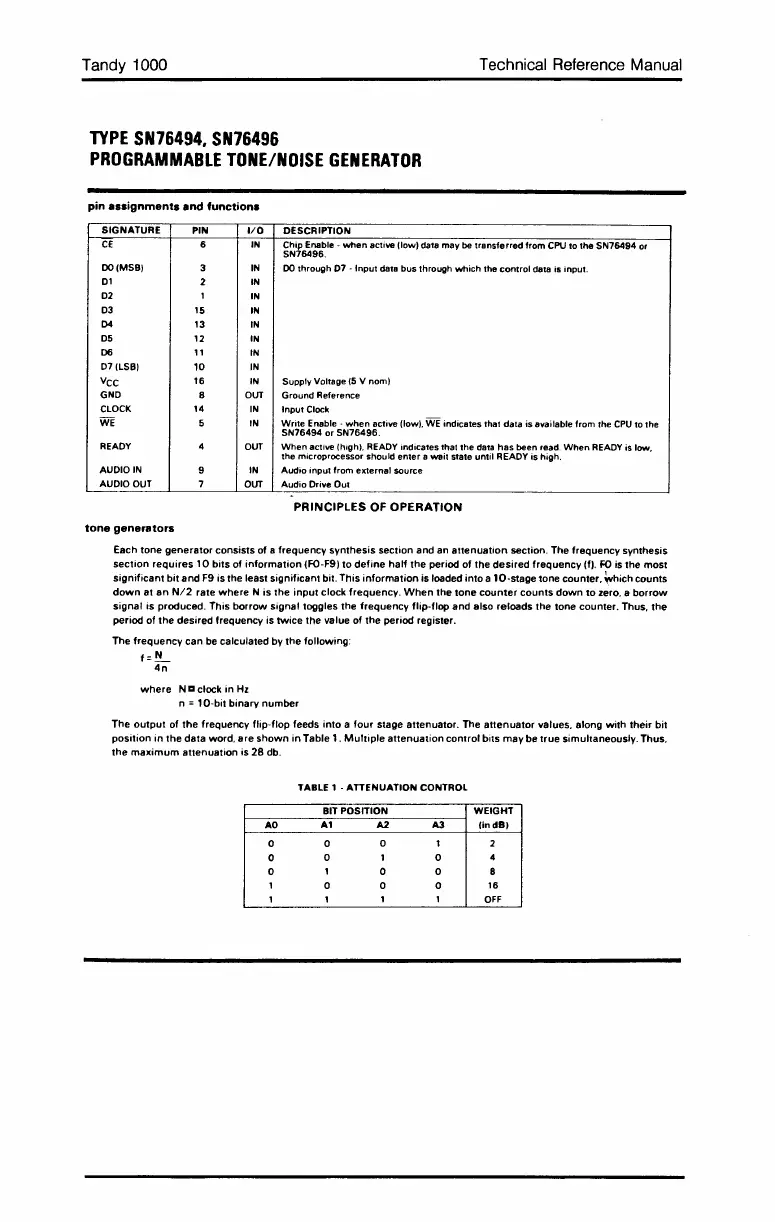
pin
assignments
and
functions
Technical Reference Manual
SIGNATURE
PIN
I/O
CE
6
IN
DO
(MSB)
3
IN
01
2
IN
02
1
IN
03
15
IN
D4
13
IN
05
12
IN
D6
11
IN
07
(LSB)
10
IN
VCC
16
IN
GND
8
OUT
CLOCK
14
IN
WE
5
IN
READY
OUT
AUDIO
IN
IN
AUDIO
OUT
OUT
tone
generators
DESCRIPTION
Chip Enable - when
active (low) data may
be
transferred from
CPU
to the SN76494
or
SN76496.
DO
through
07
- Input data bus through which the control data is input.
Supply Voltage
(5
V nom)
Ground Reference
Input
Clock
Write
Enable
- when active (low).
WE
indicates that data is available from the
CPU
to the
SN76494 or SN76496.
When
active (hIgh).
READY
indicates thai the
data
has been
read.
When
READY
is
low.
the microprocessor should
enter
a
wait
sta1e until
READY
is
high.
Audio input from external source
Audio Driye Out
PRINCIPLES
OF
OPERATION
Each
tone
generator
consists
of
a
frequency
synthesis
section
and
an
attenuation
section.
The
frequency
synthesis
section
requires
1Q
bits
of
information
(FO-F9)
to
define
half
the
period
of
the
desired
frequency
(f).
~
is
the
most
significant
bit
and
F9
is
the
least
significant
bit.
This
information
is
loaded
into
a
10·stage
tone
counter.
~hich
counts
down
at
an
N/2
rate
where
N
is
the
input
clock
frequency.
When
the
tone
counter
counts
down
to
zero. a
borrow
signal
is
produced.
This
borrow
signal
toggles
the
frequency
flip-flop
and
also
reloads
the
tone
counter.
Thus.
the
period
of
the
desired
frequency
is
twice
the
value
of
the
period
register.
The
frequency
can
be
calculated
by
the
following:
f=!!-
4n
where
N a
clock
in
Hz
n
= 1
Q·bit
binary
number
The
output
of
the
frequency
flip-flop
feeds
into
a
four
stage
attenuator.
The
attenuator
values.
along
with
their
bit
position
in
the
data
word.
are
shown
in
Table
1.
Multiple
attenuation
control
bits
may
be
true
simultaneously.
Thus.
the
maximum
attenuation
is
28
db.
TABLE 1 - ATTENUATION CONTROL
BIT POSITION WEIGHT
AO
A1
A2
A3
lindSI
0 0
0 t 2
0
0 1 0
4
0
1
0 0
8
1
0 0 0
16
1 1
1 1
OFF
 Loading...


