EasyManuals Logo

Tandy 1000 Technical Reference Manual

Default Icon
497 pages
To Next Page IconTo Next Page
To Previous Page IconTo Previous Page
Page #404 background imageLoading...
Page #404 background image
Tandy 1000
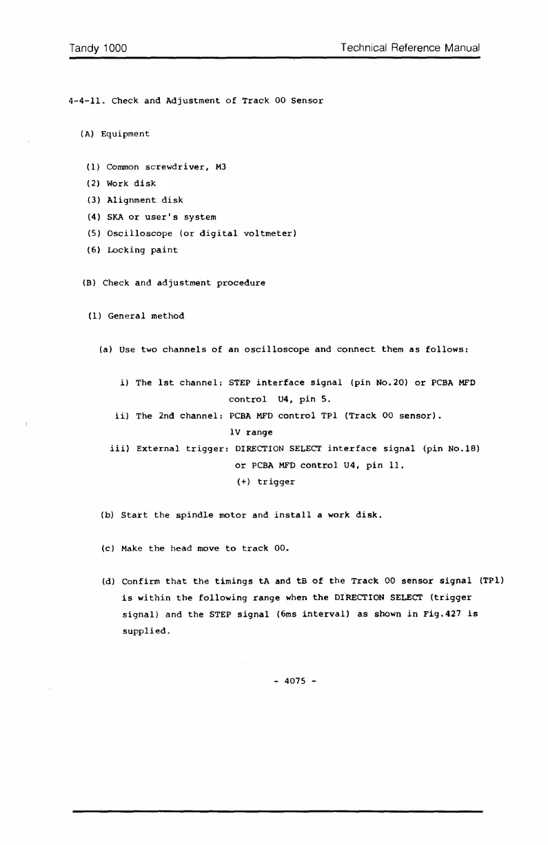
4-4-11.
Check
and
Adjustment
of
Track
00
Sensor
(A)
Equipment
(1)
Common
screwdriver,
M3
(2)
Work
disk
(3)
Alignment
disk
(4)
SKA
or
user's
system
(5)
Oscilloscope
(or
digital
voltmeter)
(6)
Locking
paint
(B)
Check
and
adjustment
procedure
(1)
General
method
Technical Reference Manual
(a)
Use
two
channels
of
an
oscilloscope
and
connect
them
as
follows:
i)
The
1st
channel:
STEP
interface
signal
(pin
No.20)
or
PCBA
MFD
control
U4,
pin
5.
ii)
The
2nd
channel:
PCBA
MFD
control
TPI
(Track
00
sensor).
IV
range
iii)
External
trigger:
DIRECTION SELECT
interface
signal
(pin
No.lS)
or
PCBA
MFD
control
U4,
pin
11.
(+)
trigger
(b)
Start
the
spindle
motor
and
install
a
work
disk.
(c)
Make
the
head
move
to
track
00.
(d)
Confirm
that
the
timings
tA
and
tB
of
the
Track
00
sensor
signal
(TPl)
is
within
the
following
range
when
the
DIRECTION SELECT
(trigger
signal)
and
the
STEP
signal
(6ms
interval)
as
shown
in
Fig.427
is
supplied.
-
4075
-

Table of Contents

Other manuals for Tandy 1000

Questions and Answers:

Question and Answer IconNeed help?

Do you have a question about the Tandy 1000 and is the answer not in the manual?

Tandy 1000 Specifications

General IconGeneral
ProcessorIntel 8088
Processor Speed4.77 MHz
RAM128 KB (expandable to 640 KB)
Operating SystemMS-DOS 2.11
ManufacturerTandy Corporation
Release Year1984
StorageSingle or double 5.25" floppy disk drive (360 KB), optional hard drive
SoundTandy 3-voice sound
PortsParallel, Serial
GraphicsCGA (Color Graphics Adapter)
Graphics Modes320x200, 640x200

Related product manuals