23
Models PH71/PH84 Operating Procedures
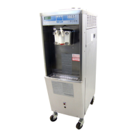
Make sure the beater assembly is in position over the
drive shaft. Turn the beater slightly to be certain that
the beater is properly seated. When in position, the
beater will not protrude beyond the front of the freezing
cylinder.
Figure 7
Duplicate these procedures for the other side of
the freezer on the Model PH84.
Step 3
Assemble the freezer door . Place the large rubber
gasket(s) in the groove(s) on the back side of the
freezer door .
Slide the white plastic front bearing(s) onto the bearing
hub(s), making certain that the flanged end of the
bearing is resting against the freezer door. DO NOT
lubricate the gasket(s) or the front bearing(s).
Figure 8
Note: There are two gaskets and two front bearings
for the Model PH84 door , one for each freezing
cylinder.
Step 4
Install the freezer door. Insert the baffle rod(s) through
the opening in the beater assembly(ies) and seat the
door flush with the freezing cylinder(s). With the door
seated on the freezer studs, install the handscrews.
T ighten equally in a criss-cross pattern to insure the
door is snug.
Figure 9
Note: On the Model PH84, the short handscrews go
on the bottom and the long handscrews go on top.
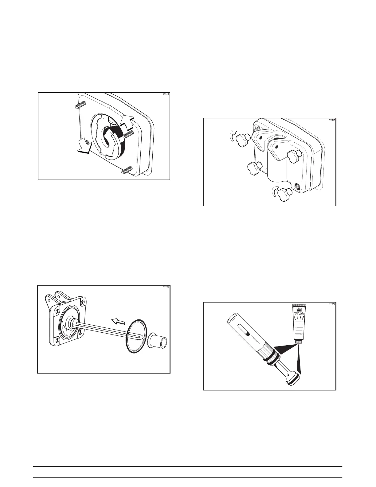
Step 5
Install the draw valve(s). Slide the three o-rings into the
grooves on the draw valve(s) and lubricate.
Figure 10