57
Model PH90 Operating Procedures
Step 8
Install the knob with the knob o- ring onto the threaded
end of the plunger assembly. Hold the plunger
assembly so that the plunger tube, compressing the
spring, is pulled toward the piston end as far as it will
go. Tighten the knob by turning it clockwise.
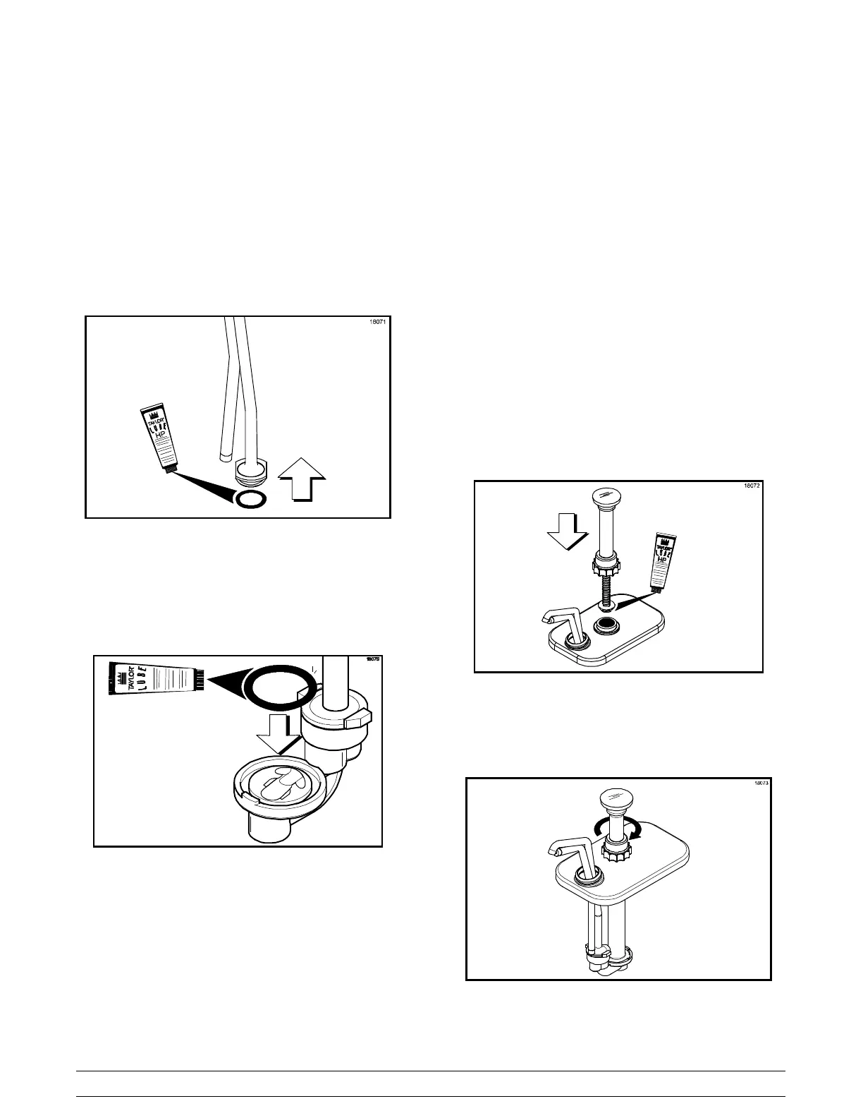
Step 9
Lubricate and install the 1” o- ring onto the groove
provided on the discharge tube.
Figure 120
Step 10
Lubricate and install the 1- 5/16” o- ring into the valve
body.
Figure 121
Step 11
Install the discharge tube onto the smaller opening in
the valve body by aligning the flats on the discharge
tube with the locking grooves on the valve body. Push
down the discharge tube until it is seated into the valve
body opening. Turn the discharge tube clockwise to
fully engage it into locking grooves on the valve body.
Step 12
Install the cylinder onto the larger opening in the valve
body by tilting the cylinder away from the discharge
tube and sliding the widest section of flange under the
center locking groove on the valve body. Align the tabs
on the cylinder with the locking grooves on the valve
body. T urn the cylinder clockwise until the tabs fully
engage into the locking grooves on the valve body.
Step 13
Install the lid by inserting the discharge tube through
the smaller hole in the lid. Slide the lid until the larger
hole fits around the top of the cylinder. The discharge
tube lock nut will secure the lid in position.
Step 14
Install the discharge tube lock nut.
Step 15
Lubricate and install the plunger assembly into the
cylinder opening in the pump body.
Figure 122
Step 16
T ighten the plunger nut by turning it clockwise.
Figure 123