User Manual Chapter 7 - Parameters Description 115
In the PID menu are contained all the parameters concerning the setting of the function.
The DVS drive provides a PID function, engineered on purpose for the following controls:
nip rolls with dancer or load cell
pressure regulation for pumps and extruders
speed loop control with encoder
A use of the PID block as stand-alone is also possible, correlated (or not) to the RUN status of the drive.
PID
V/F
A.001
PID refence selector
Null = 0
Analog input1=1
Analog input2=2
Analog input3=3
Frequency ref = 4
Ramp output = 5
Digital ref = 6
Encoder frequency = 7
A.001
Reference
A.002
Feed-back
A.002
PID feedback
Null = 0
Analog input1=1
Analog input2=2
Analog input3=3
Encoder freq. = 4
Output curr = 5
Output torque = 6
Output power = 7
A.000 = 2
(Without feed-forward)
A.000
PID mode
Disable = 0
Freq. sum = 1
Freq. direct = 2
Volt sum = 3
Volt direct = 4
Stand alone = 5
St-stand alone = 6
+
-
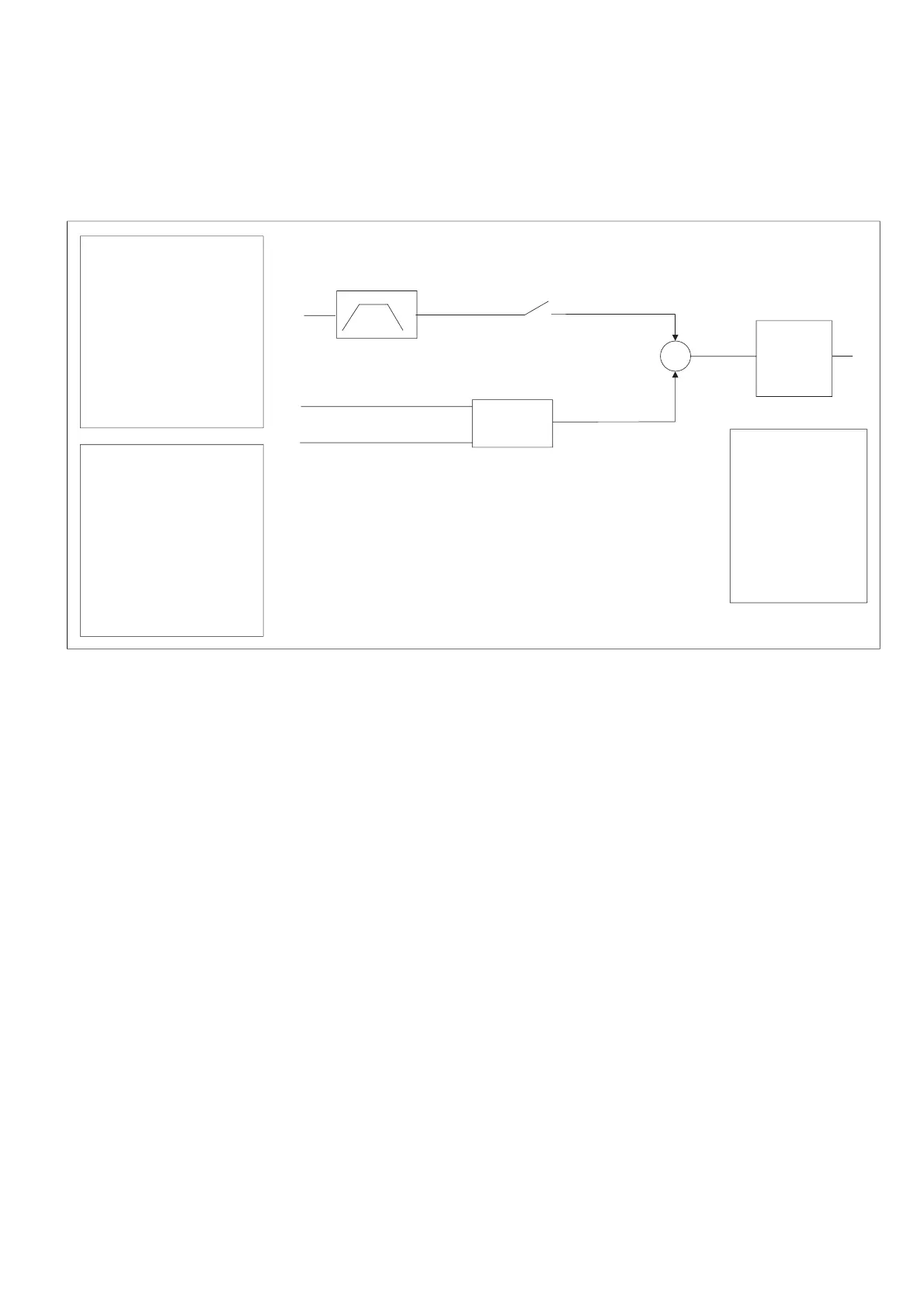
Figure 7.7.2: PID Mode as Frequency Sum or Direct
A.000 PID Mode
This parameter allows to define the regulation mode of the PID function.
A.000 = 0 Disable The function is disabled.
A.000 = 1 Freq.sum The output of the PID regulator is added to the ramp output reference value
(with feed-forward).
A.000 = 2 Freq.direct The PID regulator output is directly input to the V/f profile generator. Frequency
ramp output is not used.
A.000 = 3 Volt sum The PID regulator output is added to the voltage reference, calculated in
accordance with the setting of the V/F ratio (with feed-forward).
A.000 = 4 Volt direct The PID regulator output is the voltage to be applied to the motor. V/f curve is
not used.
A.000 = 5 Stand alone The PID function can be used as generic control. The regulator will be active
only when the drive will be in RUN.
A.000 = 6 St-Al always The PID function can be used as generic control. The regulator is not correlated
to the drive status.