37
83532002 Rev C
The Protective Earth Ground must be connected before applying
AC Line Power to the Power Supply.
3.8. Turn-On Checkout Procedure
3.8.1. General
The following procedure ensures that the Power Supply is operational and may be
used as a basic incoming inspection check. Refer to Fig. 4-1 and Fig. 4-2 for the
location of the controls indicated in the procedure.
3.8.2. Prior to Operation
a) Ensure that the Power Supply is configured to the default setting:
AC On/Off switch at the Off position.
Dip switch (SW1): All positions at Down (“Off”) position.
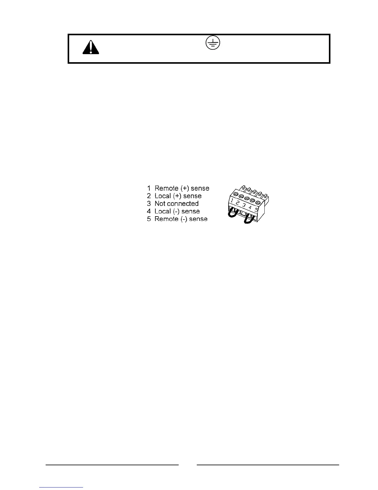
Remote Sense connector (J2): configured to Local Sense (as shown in Fig.3-2)
Figure 3-2: Sense connector default connection
For units equipped with IEEE option, ensure that the IEEE_Enable switch is in
the UP (default) position (Refer to Fig. 4-2, Item 9 for location) if Turn-On
checkout is to be done in IEEE mode.
b) Connect the unit to an AC power source as described in Section 3.7.
c) Connect a DVM with appropriate cables for the rated Output voltage across the
DC Output terminals.
d) Press the front panel AC ON/OFF switch to the On position.
3.8.3. Constant Voltage Check
a) Turn on the output by pressing the OUT pushbutton (the front panel OUT LED
should illuminate).
b) Observe the Power Supply VOLT display and rotate the Voltage encoder. Ensure
that the Output voltage varies while the VOLT encoder is rotated. The minimum
control range is from zero to the maximum rated Output voltage for the power
supply model.
c) Compare the DVM reading with the front panel VOLT display to verify the
accuracy of the VOLT display. Ensure that the front panel VOLT LED is On.
d) Press the front panel AC ON/OFF power switch to the Off position.
3.8.4. Constant Current Check
a) Ensure that the front panel AC ON/OFF switch is set to the Off position and the
DVM connected to the output terminals shows zero Output voltage.
b) Connect a DC shunt across the output terminals. Ensure that the shunt and the
wire voltage and current ratings are higher than the Power Supply Output voltage
and Output current ratings. Connect a DVM across the shunt.