73
83532002 Rev C
7.3. Local/Remote Analog Indication
J1-21 (Fig. 4-4) is an open collector output that indicates if the Power Supply is in Local
mode or in Remote Analog mode. To use this output, connect a pull-up resistor to a voltage
source of 30VDC maximum. Choose the pull-up resistor so that the sink current will be less
than 5mA when the output is in the low state. Refer to Table 7-2 for the J1-21 function.
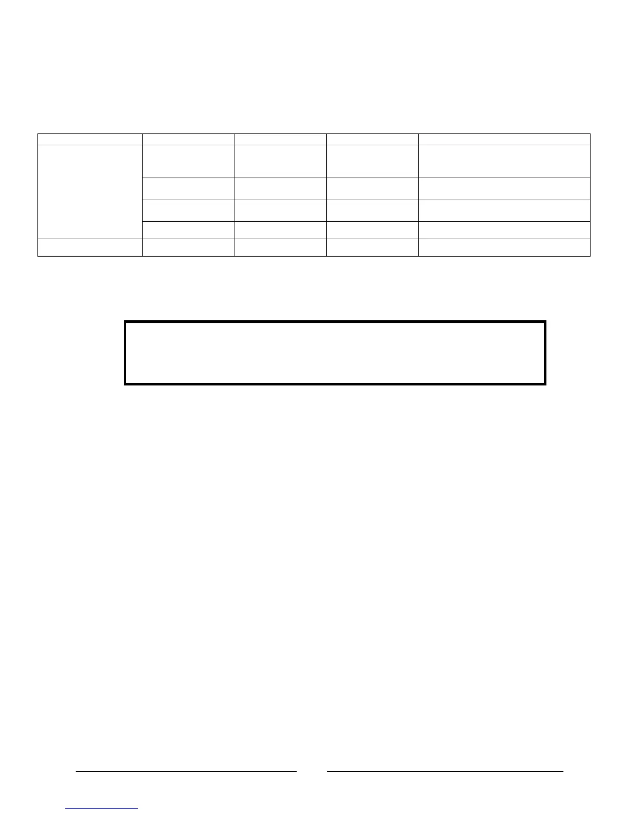
J1-8 SW1-1 SW1-2 J1-21 signal
Analog Mode
TTL “0” or short
Down Down Open Local: Voltage/Current programming
Down Up 0-0.6V
Local: Voltage programming
Remote: Current programming
Up Down 0-0.6V
Remote: Voltage programming
Local: Current programming
Up Up 0-0.6V Remote: Voltage/Current programming
TTL “1” or open
Down or Up Down or Up Open Local: Voltage/Current programming
Table 7-2: Local/Remote Analog indication
7.4. Remote Voltage Programming of Output Voltage and Current Limit
CAUTION
To maintain the isolation of power supply and prevent ground loops, use an
isolated programming source when operating the power supply via Remote
Analog programming at the J1 connector.
Perform the following procedure to set the Power Supply to Remote Voltage programming:
a) Turn the AC On/Off power switch to the OFF position.
b) Set SW1-1 to the UP position for Output voltage external programming and SW1-2 to the
UP position for Output current external programming.
c) Set SW1-3 to select the programming Voltage Range according to Table 7-3.
d) Ensure that SW1-7 and SW1-8 are in their DOWN (default) position.
e) Connect a wire jumper between J1-8 and J1-12 (refer to Table 4-4).
f) Connect the programming sources to the mating plug of J1 as shown in Fig.7-1. Observe
the correct polarity for the voltage source.
g) Set the programming sources to the desired levels and turn On the AC On/Off power
switch. Then adjust the programming sources to change the power supply output level(s).
NOTES:
1. SW1-4, -5, -6 and -9 are not required for Remote Analog programming. Their
settings can be determined according to the application.
2. The control circuits allow the user to set the Output voltage and Output current limit
up to 5% over the model-rated maximum value. The Power Supply will operate
within the extended range, however it is not recommended to operate the power
supply outside of its Output voltage and Output current rating and performance is
not guaranteed.