58
83532002 Rev C
Table 5-1: SO Logic Selection
5.8. Enable/Disable Control via Rear Panel J1 Connector
J1-1 and J1-14 (Fig.4-4) serve as the Output Enable/Disable terminals by switch or relay.
This function is enabled or disabled by SW1-9. Refer to Table 5-2 for the Enable/Disable
function and SW1 settings.
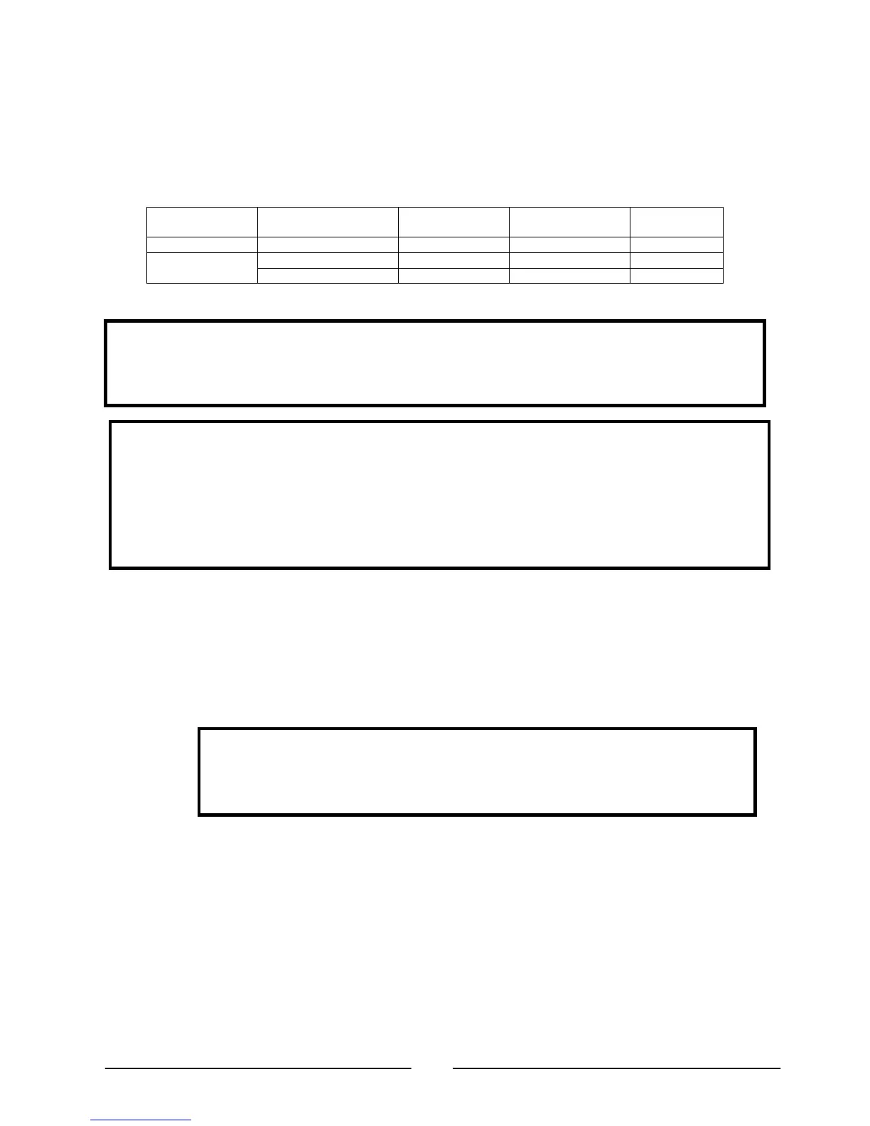
SW1-9 setting Enable/Disable
inputs
Power supply
output
Display ALARM LED
Down (Default) Open or Short On Voltage/Current Off
Up
Open Off “ENA” Blinking
Short On Voltage/Current Off
Table 5-2: Enable/Disable function and SW1 setting
5.9. CV/CC Signal
The CV/CC signal indicates the operating mode of the Power Supply, Constant-Voltage
or Constant-Current. The CV/CC signal is an open collector output with a 30V parallel
zener, at J1-13 and referenced to the COM potential at J1-12 (connected internally to the
negative local sense potential). When the power supply operates in Constant Voltage
mode, the CV/CC output is open. When the Power Supply operates in Constant-Current
mode, the CV/CC signal output is low (0-0.6V), with a maximum sink current of 10mA.
CAUTION
DO NOT connect the CV/CC signal to a voltage source higher than 30VDC.
Always connect the CV/CC signal to a voltage source with a series resistor to
limit the sink current to less than 10mA.
5.10. PS_OK Signal
The PS_OK signal indicates a fault condition in the Power Supply. PS_OK is a TTL signal
output at J1-16, referenced to IF_COM at J1-2, 3 (Isolated Interface Common). When a
fault condition occurs, the PS_OK level is low with a maximum sink current of 1mA.
When no fault condition occurs, the PS_OK level is high with a maximum source current
of 2mA. The following faults will set the PS_OK to a fault state:
*OTP *Enable/Disable open (power supply is disabled)
*OVP *SO (Rear panel Shut-Off, power supply is shut off)
*Foldback *IEEE failure (With optional IEEE interface)
*AC Fail *Output Off (by front panel or remote command)
CAUTION
To prevent possible damage to the unit, DO NOT connect any of the Enable/Disable inputs
ositive or negative output potential.
If the Enable/Disable inputs are opened when the unit is in Safe-Start mode, it is required to
short the Enable/Disable inputs and then press the OUT button or send the “OUT 1”
command to resume operation.
If the Enable/Disable inputs are opened when the unit is in Auto-Restart mode, it is required
to short the Enable/Disable inputs and then the output will turn NOTE