46
83532002 Rev C
4. FRONT AND REAR PANEL CONTROLS AND CONNECTORS
4.1. Introduction
The Genesys
TM
Power Supply series has a full set of controls, indicators and connectors
that allow the user to easily setup and operate the unit. Before starting to operate the
unit, please read the following sections for explanation of the functions of the controls and
connectors terminals:
- Section 4.2: Front Panel Controls and Indicators.
- Section 4.3: Rear Panel Connections and Controls.
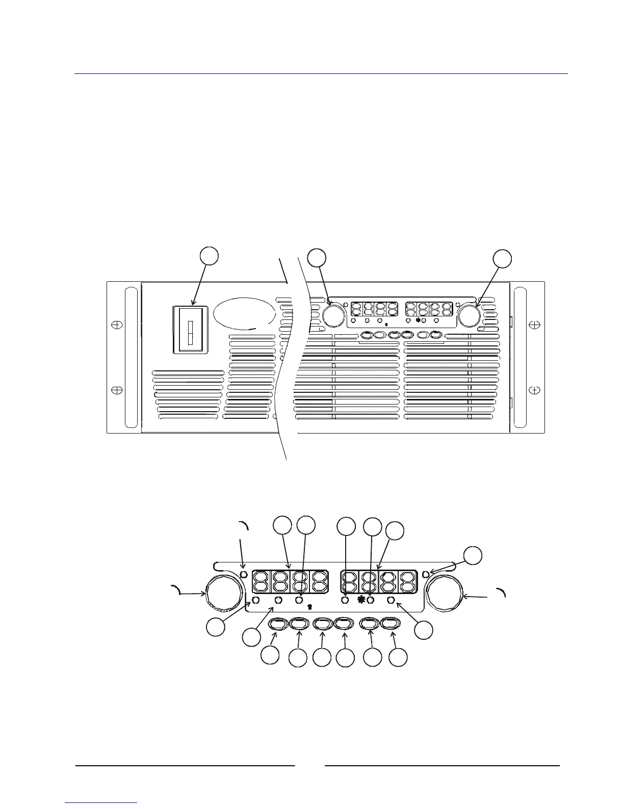
4.2. Front Panel Controls and Indicators
See Figure 4-1 to review the controls, indicators and meters located on the Power Supply
front panel.
AL ARM
FIN E PREV/
OVP
UVL
FOL D
OU T
DC VOLTS
CURRENT
GENESYS POWERSUPP
L
Y
TM
19
1
12
10
4
8
VOLTAGE
ALARM
FINE PREV/
OVP
UVL
FOLD REM/LOC OUT
DC VOLTS
CURRENT
L
Y
1
2
Fig. 4-1: Front Panel Controls and Indicators.