48
83532002 Rev C
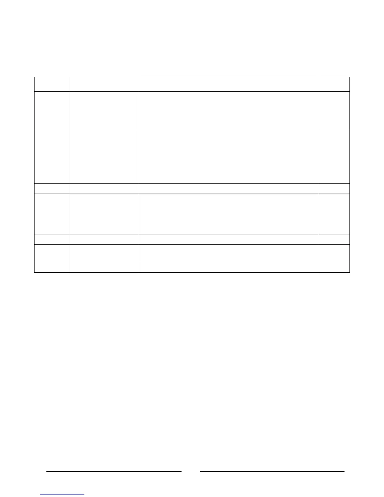
Table 4-1: Front Panel Controls and Indicators (Cont.)
Number Control/Indicator Description Section
13 OVP/UVL button Over Voltage Protection and Under Voltage limit setting.
-Press once to set OVP using the VOLTAGE encoder (the current
display shows “OUP”)
-Press again to set the UVL using the VOLTAGE encoder (the
current display shows “UUL”).
5.3
5.4
14 PREV button Main function: Press PREV to display the Output voltage and
current limit setting. For 5 seconds the display will show the setting
and then it will return to show the actual Output voltage and current.
Auxiliary function: Front Panel Lock. Press and hold PREV button
to toggle between “Locked front panel” and “Unlocked front panel”.
The display will cycle between “LFP” and “UFP”. Releasing the
PREV button while one of the modes is displayed selects that mode.
5.12
15 PREV indicator Green LED, lights when PREV button is pressed
16 FINE button Main function: Voltage and Current Fine/Coarse adjustment control.
Operates as a toggle switch. In Fine mode, the VOLTAGE and
CURRENT encoders operate with high resolution and in Coarse
mode with lower resolution (approx. 6 turns).
Auxiliary function: Advanced Parallel Operation Mode Setting.
6.4
17 FINE indicator Green LED, lights when the unit is in Fine mode.
18 ALARM indicator Red LED, blinks in case of fault detection. OVP, OTP, Foldback,
Enable and AC fail detection will cause the ALARM LED to blink.
19 AC Power Switch AC ON/OFF Control
4.3. Rear Panel Connections and Controls
See Fig. 4-2 to review the connections and controls located on the Power Supply rear panel.
Refer to Table 4-2 for explanations about the rear panel connections and controls.