42
83532002 Rev C
Fig. 3-3: Single load connection, local sensing
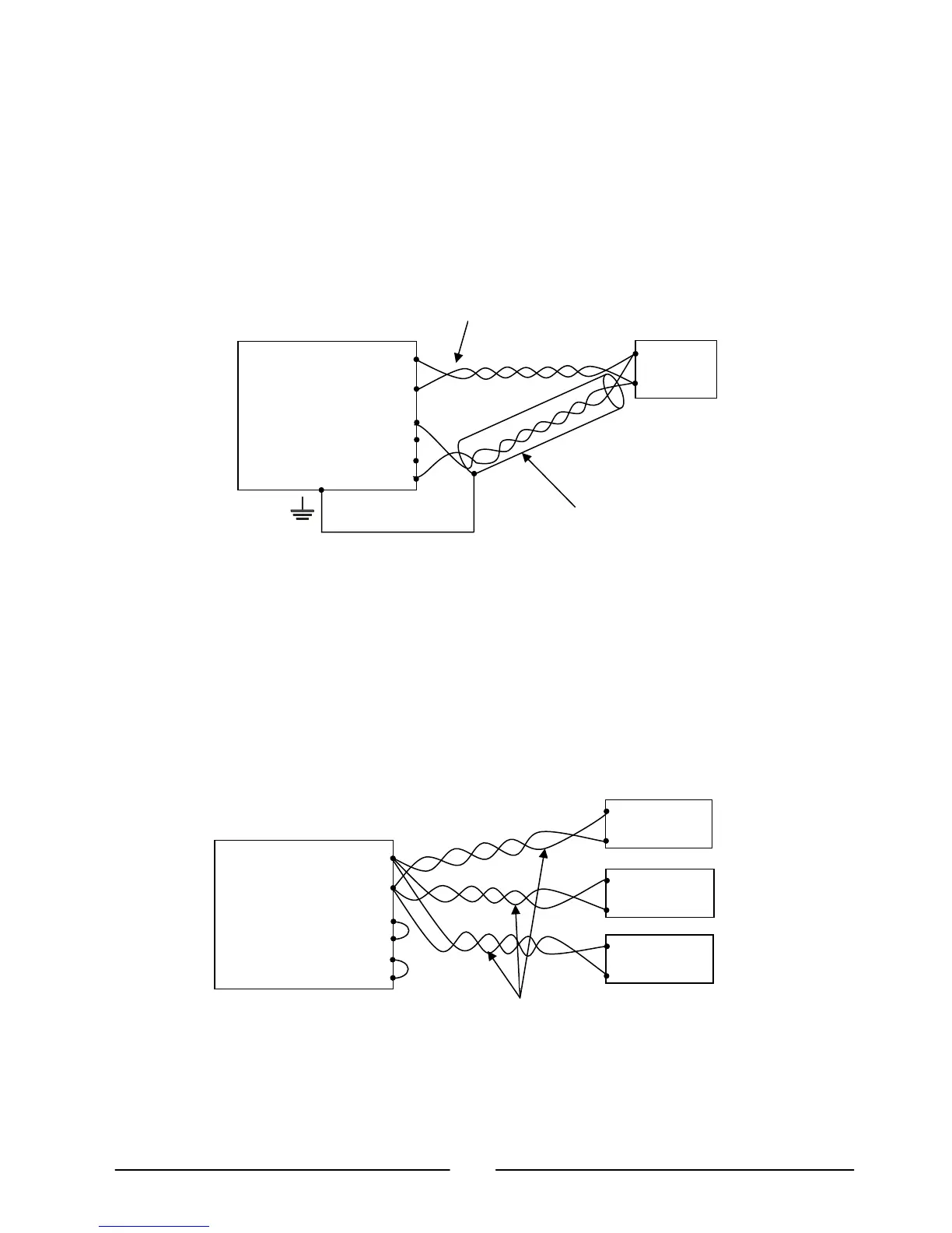
3.9.7. Connecting Single Loads, Remote Sensing
Fig.3-4 shows the recommended remote sensing connection for single loads. Remote
sensing is used when, in Constant-Voltage mode, the load regulation is important at
the load terminals. Use twisted or shielded wires to minimize any noise pick-up. If
shielded wires are used, the shield should be connected to the ground at one point,
either at the Power Supply chassis or the load ground. The optimal point for the
shield ground should be determined by experimentation.
Fig. 3-4: Remote sensing, single load
3.9.8. Connecting Multiple Loads, Radial Distribution Method
Figure 3-5 shows multiple loads connected to one Power Supply. Each load should
be connected to the power supply’s output terminals using separate pairs of wires. It
is recommended that each pair of wires will be as short as possible and twisted or
shielded to minimize noise pick-up and radiated noise. The sense wires should be
connected to the Power Supply Output busbars/threaded-studs or to the load with the
most critical load regulation requirement.
Fig. 3-5: Multiple loads connection, radial distribution, local sense
-Rem Sense
-Local Sense
+Local Sense
+Rem Sense
Power
Load Lines, twisted pair,
shortest length possible.
Sense lines.
Twisted Pair
-Rem Sense
-Local Sense
+Local Sense
+Rem Sense
Power
Load Lines, twisted pair,
shortest length possible.