To get access again by another IP address, once a power reset is needed in another
Rotary switch position than “F”.
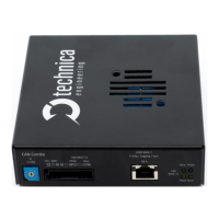
2.2.2 Status LEDs
The CM_CAN_Combo has several status LEDs at the front side of the case.
Figure 2-5: LED allotment on front of the device
Right side:
LED F:
The “FPGA” LED toggles (approx. 2 sec) during normal operation. If it is not blinking
or blinking faster, FPGA is damaged and must be repaired
LED H:
The “Host” LED can toggle at two different speeds:
o Slow toggle (approx. 1 sec) during normal operation
o Fast toggle (approx. 0.2 sec) if device is in Bootloader mode
Left side:
These LEDs show the status of the connected devices to the 100BASE-T1-Port
LED H:
Connection to the Host/Microprocessor (1)
LED F:
Connection to the FPGA (2)
LED “on” (static) indicates LinkUp
LED blinking means communication on 100BASE-T1 Port