AccuLoad IV Installation & Maintenance Manual
Pre-Installation Considerations 15
• Two separate AC circuits must be provided from the breaker panel. One circuit should supply isolated
power to the AccuLoad’s electronics (instrument power). The second circuit should supply power to
external devices (Section 3.6.1: AC Input Power).
• For proper operation, the AccuLoad must be earth grounded. The grounding point should be as close
to the unit as possible.
• To ensure proper earth grounding, the resistance between the ground lug in the AccuLoad and the
grounding point must not exceed 2 Ω. The proper grounding point is a ½- to ¾-inch diameter copper
stake that extends into the water table. Where this is not practical, a ground plane may be used.
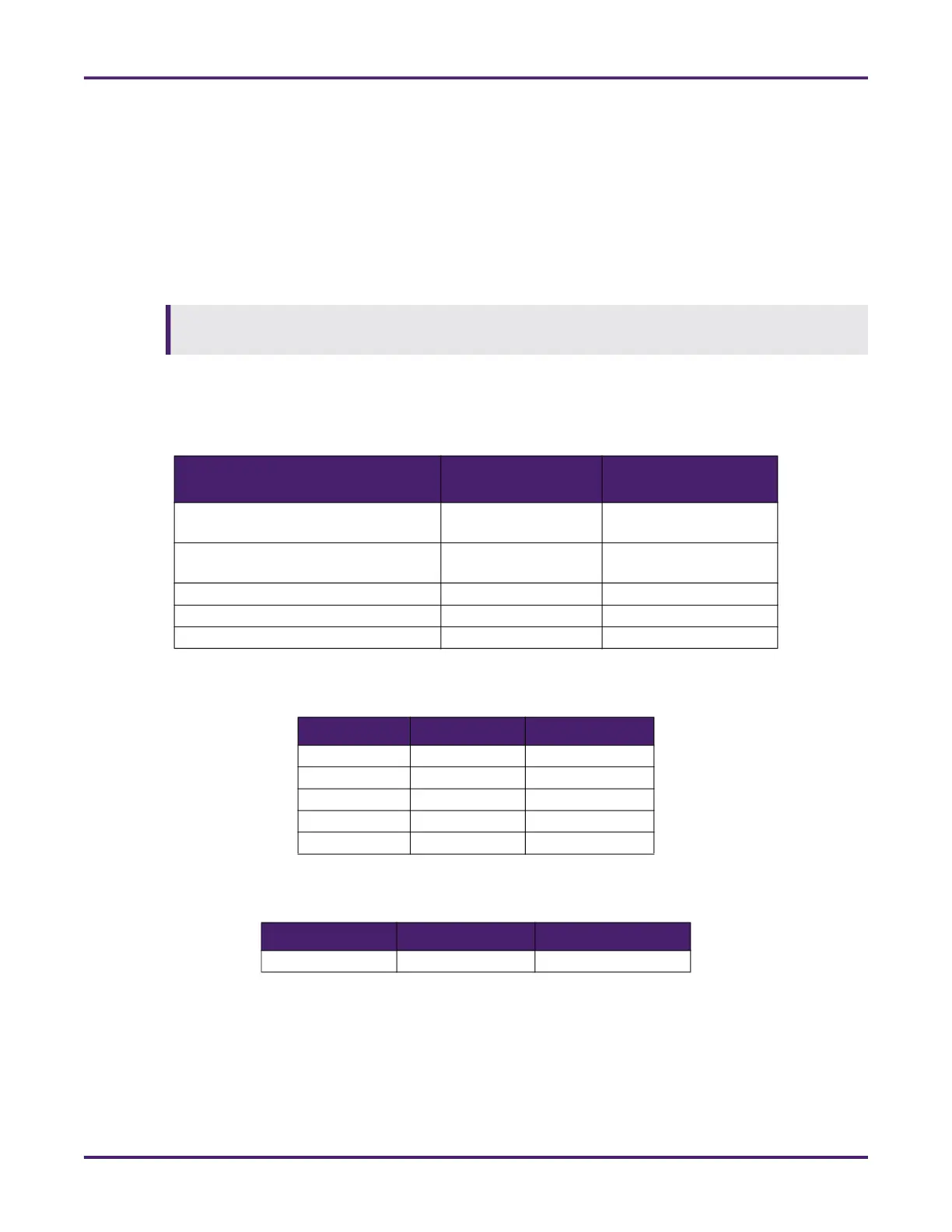
2.5.1 Typical Wire Sizes and Cable Lengths
See the following tables for typical wire sizes, cable lengths, and baud rates.
Electrical conduit, piping, and structural steel are not considered proper grounding points for
equipment using electronics.
Table 4: Typical Wire Sizes
Equipment
Number and Gauge
of Wire
Belden Number or
Equivalent
Transmitters 4/18 gauge
4/20 gauge
9418
8404
Temperature probes
Density and pressure transmitters
4/22 gauge 8729 or 9940
EIA-232 3/24 gauge 9533
EIA-485 Communications 4/24 gauge 9842
Ethernet Cat 5 or Cat 6 1584A or 2412
Table 5: Serial Communications (EIA-232) Maximum Cable Length and Baud Rate
Baud Rate Feet Meters
115,200 62.5 18.25
57,600 125 37.5
38,400 250 75
19,200 500 150
9,600 1,000 305
Table 6: Serial Communications (EIA-485) Maximum Cable Length and Baud Rate
Baud Rate Feet Meters
9,600 to 115,200 4,000 1,220