AccuLoad IV Installation & Maintenance Manual
Installation 20
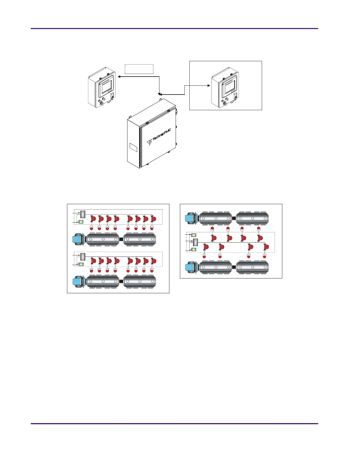
Each MMI is connected to its MMIs by Ethernet or serial cables.
The FCM unit can be installed at a location that is convenient to service personnel. The MMI units can be
installed for convenient access by drivers. Typical installation approaches are shown below.
3.5 Electronic Layouts and Connections
This section provides wiring information and drawings for the SA model’s units, as well as all of the
AccuLoad’s electronic modules.
3.5.1 FCM Unit
The FCM unit contains between one and four board sets to provide control of up to 24 loading arms. Each
board set consists of an A4M module, an A4B module, and an optional A4I module. These board sets are
mounted in the FCM enclosure, as shown below in Figure 11: SA Model FCM components.
Figure 9: AccuLoad IV Split Architecture Units
Ethernet
Optional
MMI
MMI
FCM
Figure 10: Typical Installations for AccuLoad IV SA
Lane Two
FCM
MMI
FCM
MMI
Lane One
Lane One
FCM
MMI
FCM