AccuLoad IV Installation & Maintenance Manual
Installation 39
To insert a module, line up the pins with the socket holes, push the module in until it is seated against the
circuit board, and then tightening the retaining screw.
3.6.7 Typical Wiring Diagrams
The following diagrams provide details for wiring the AccuLoad IV.
CAUTION: Before inserting or removing any analog module, first ensure that all associated circuits are
de-energized. Use proper ESD practices.To remove a module, loosen the captive retaining screw and
then gently pull the module out of the socket while slightly rocking the module.
Figure 26: Analog I/O Modules
Sockets
Analog Module
Alignment Pins
AM 1
Mounting Screw
Side View
Top View
Set Cal 1 and Cal 2
parameters to these
values in AccuLoad
analog configuration
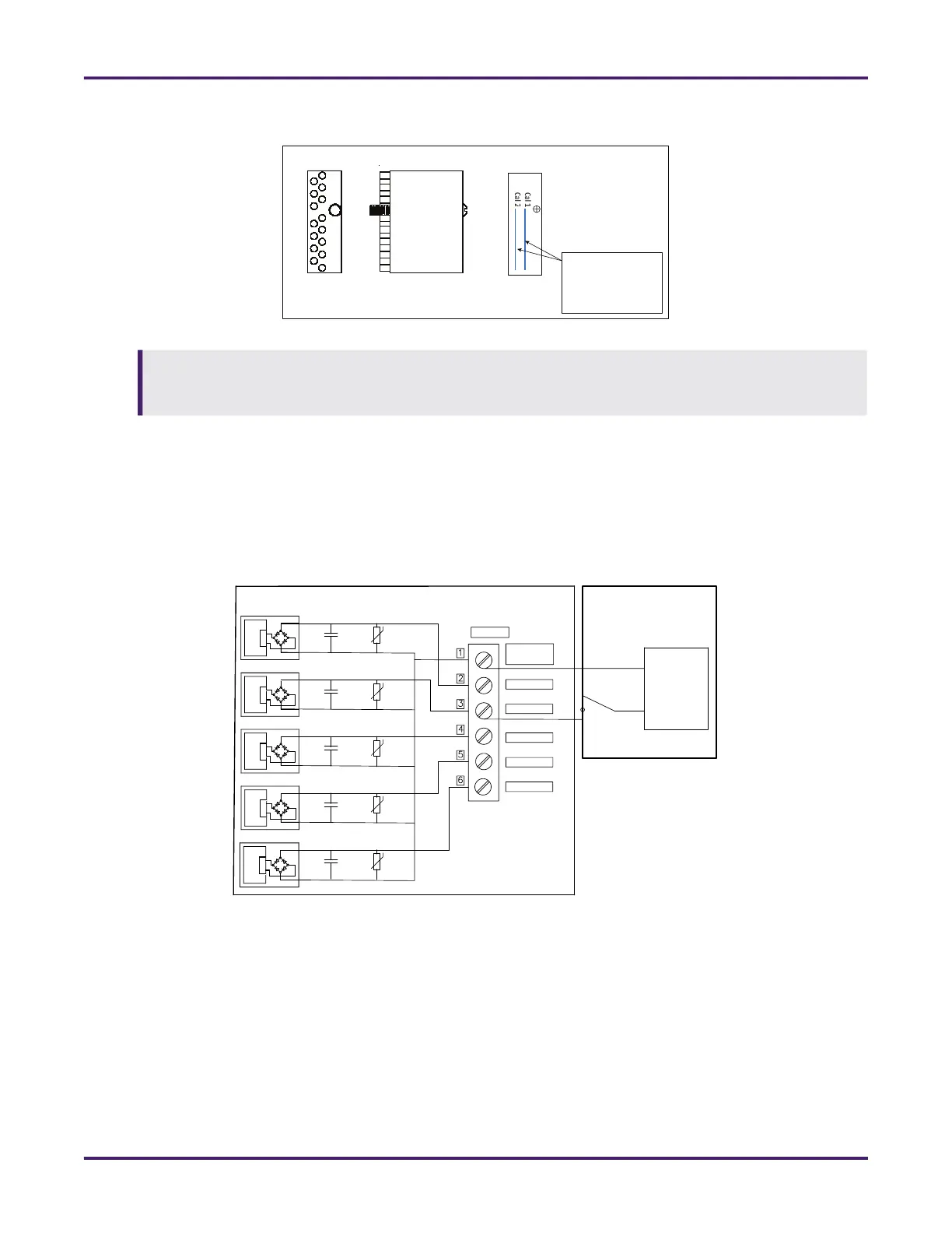
Figure 28: AC Digital Input
AccuLoad
TBE2
L2
AC supply
L1
External AC Wiring
AC
AC
AC
AC
(L2) AC IN
Common
In #7 (AC)
In #8 (AC)
In #9 (AC)
In #10 (AC)
In #11 (AC)
AC
AC
AC
AC