AccuLoad IV Installation & Maintenance Manual
Installation 42
3.7 Communications Wiring
3.7.1 Ethernet Communications
The recommended networking strategy is to place the AccuLoad on a segmented network, which isolates
the industrial control network traffic from the broader general purpose network traffic associated with
corporate LANs and the Internet. This strategy enhances the security and throughput on the critical control
portion of the network. The following figure illustrates this networking strategy.
For pulse transmitters requiring 12 VDC (such as GPST), install the P2412 converter. See the AccuLoad
Preset Accessory P2412 Converter Installation manual (MN06117) for details.
If the AccuLoad IV must be directly installed on a Class A network, the AccuLoad’s internal IP addressing
scheme must be changed to avoid address conflicts. For instructions on configuring internal IP
addresses for the ST, QT, and N4 models using the AccuLoad’s touch screen, refer to the AccuLoad IV
Operator Reference Manual (MN06200). For details about changing internal IP addresses for the SA
model using DIP switches, see Section 3.7.1.4: SA Board Set IP Addresses.
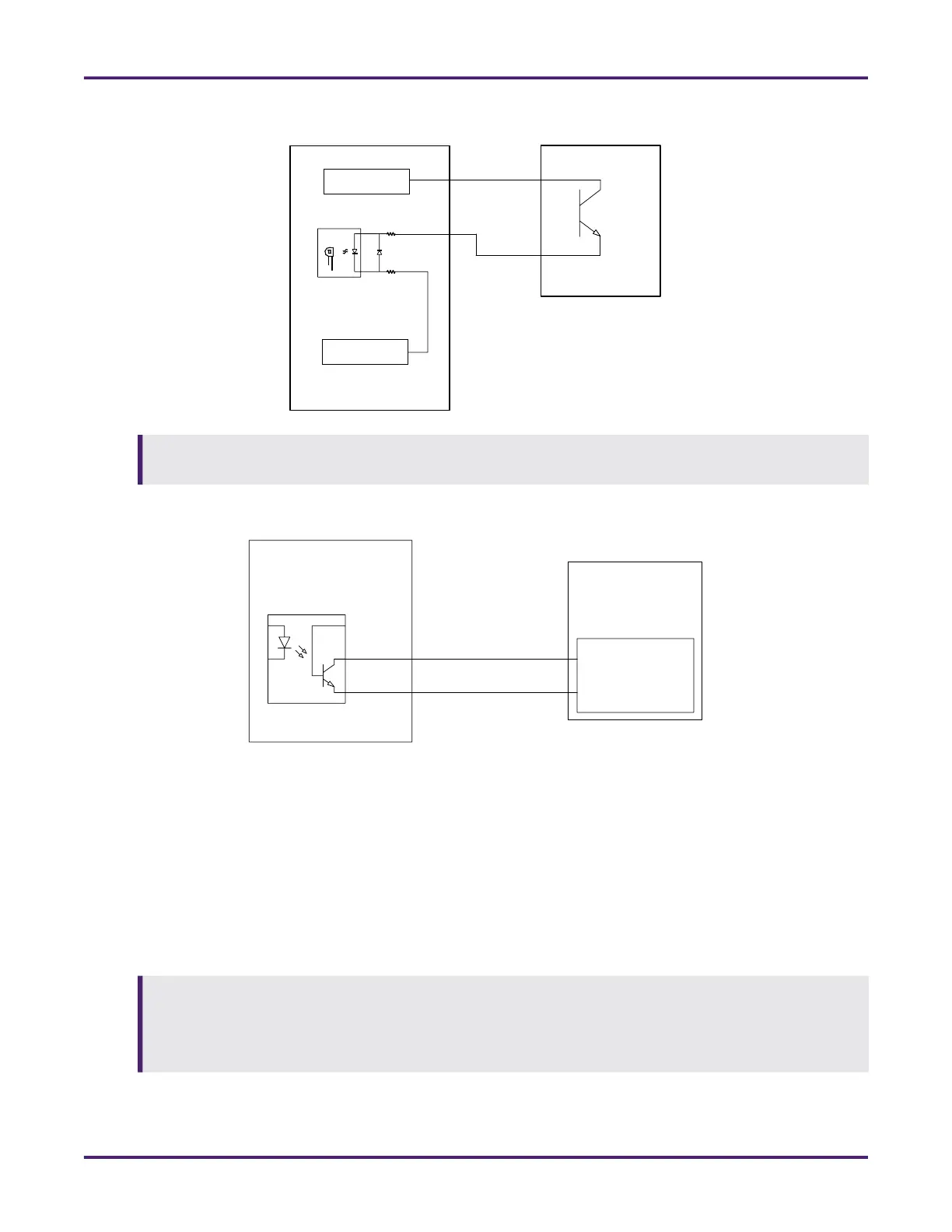
Figure 36: External Counter Wiring
IN X+
IN X-
AccuLoad
3K
3K
External Meter
Pulse Wiring
Open Collector
Meter Output
A4M +24V
TBE4 10, 11, or 12
A4M GND
TBE4 13, 14, or 15
Figure 37: High-Speed Prover Output Wiring
TBE6-1
TBE6-2
AccuLoad
External Prover
High Speed
Prover Output