AccuLoad IV Installation & Maintenance Manual
Installation 37
3.6.3 Grounding
The AccuLoad must be properly grounded to ensure safe and reliable operation.
The AccuLoad requires a single-point earth ground dedicated to the AccuLoad provided by a grounding
rod. Less than 2 ohms must be measured between the ground lug of the AccuLoad’s enclosure and the
grounding rod.
Any ground wires or shields in the cables connected to devices external to the AccuLoad (such as printers
or analog sensors) should only be connected to TBE4 terminals 13, 14, or 15 at the AccuLoad end of the
cable. It is very important to ensure this is the only grounding point.
3.6.4 I/O Connections
From the factory, none of the AccuLoad’s I/O connections or functions are defined. You must configure
your AccuLoad’s I/O points based on the equipment at your facility and the operations you want to be
performed. For example, if a digital flow control valve should to be interfaced with the AccuLoad as part of
a loading rack installation, you must configure the AccuLoad with digital outputs for the upstream and
downstream solenoids. You also must assign the upstream solenoid function to a digital output to be used
for the solenoid’s control and then do the same for the downstream solenoids.
The only I/O points that are automatically assigned by the AccuLoad are meter pulse inputs (both product
meters and additive meters). The AccuLoad assigns the pulse inputs based on the number of meters and
injectors defined in your configuration. Any pulse input which is not automatically assigned a function by
the AccuLoad is available for user-selectable functions.The pulse input assignments for various meter
configurations are provided in Section 4.3: Meter Input Wiring.
3.6.5 Meter Pulses
The AccuLoad counts pulses from the meters to determine the volume or mass that has flowed through the
meter. The AccuLoad can be configured to receive pulses in one of three modes:
• Single Channel—One pulse input receives a single stream of pulses from the meter.
• Dual Channel—Two pulse inputs receive two separate pulse streams from the meter. This enables the
AccuLoad to detect the direction of flow and meter connection problems with one of the channels so
an alarm can be raised. This also enables the AccuLoad to determine the direction of flow through the
meter.
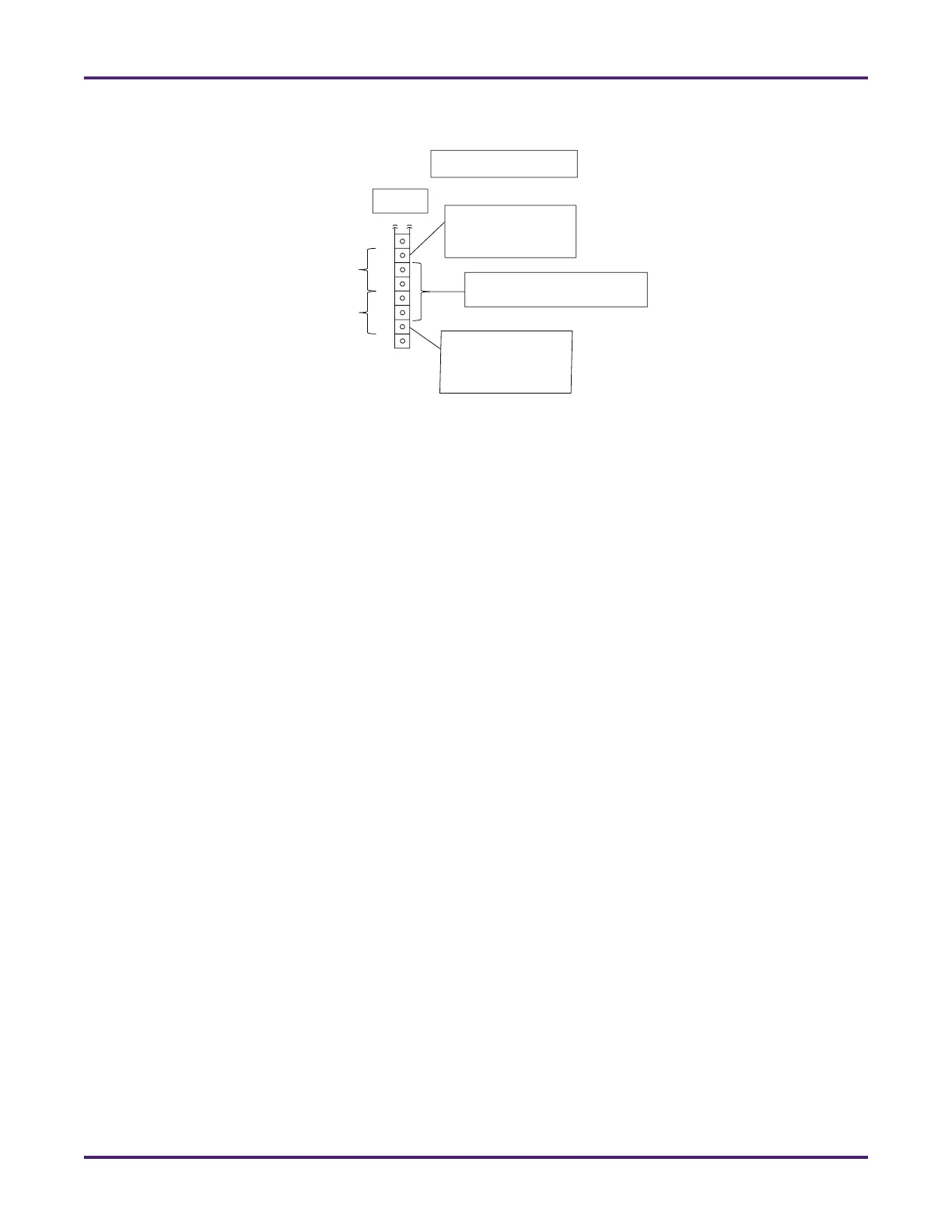
Figure 23: DC Power Wiring on ST, QT, and N4 Models
A4M Module
Factory wired to
AccuLoad internal
modules
To meter transmitters,
remote A4I etc.
Factory wired to
AccuLoad internal
modules
TBE4
+24 VDC
DC GND
9
10
11
12
13
14
15
16