AccuLoad IV Installation & Maintenance Manual
Installation 34
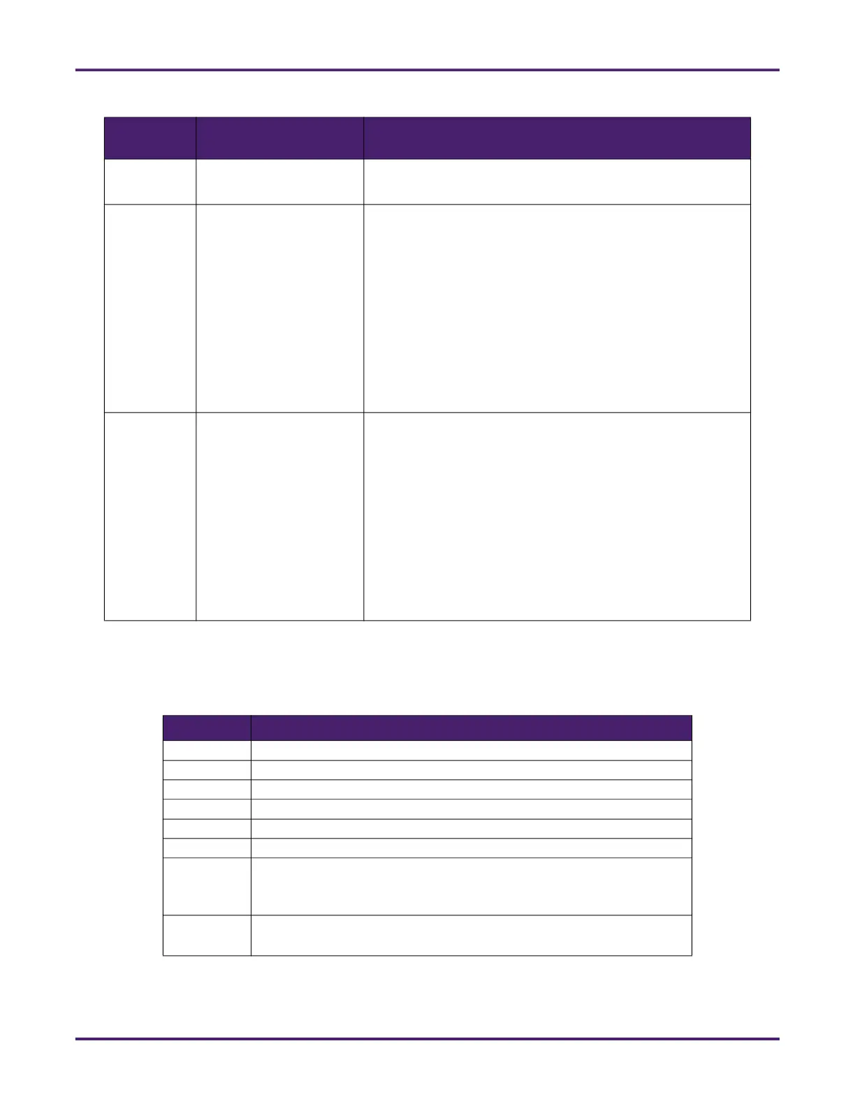
3.5.6.3 A4I DIP Switch Settings
The following table provides information about S1 DIP switch settings on the A4I board.
TB5 Serial communication port
RS485
Inj 15 in or DC In 34 – Pin 2 Inj 16 in or DC In 35 – Pin 5 Inj 17
in or DC In 36 – Pin 8
TB7 AC digital outputs AC Out 69 – Pin 10
AC Out 70 – Pin 9
AC Out 71 – Pin 8
AC Out 72 – Pin 7
AC Out 73 – Pin 6
AC Out 74 – Pin 5
AC Out 75 – Pin 4
AC Out 76 – Pin 3
AC Out 77 – Pin 2
AC Out 78 – Pin 1
TB8 AC digital outputs AC Out 59 – Pin 10
AC Out 60 – Pin 9
AC Out 61 – Pin 8
AC Out 62 – Pin 7
AC Out 63 – Pin 6
AC Out 64 – Pin 5
AC Out 65 – Pin 4
AC Out 66 – Pin 3
AC Out 67 – Pin 2
AC Out 68 – Pin 1
Table 18: A4I Switch Settings
Switch Setting
S1-1 Factory use (always OFF)
S1-2 Module address (OFF = 100, ON = 200)
S1-3 Serial baud rate (OFF = 9600, ON = 38400)
S1-4 Serial mode (OFF = RS232, ON = RS485)
S1-5 Serial termination resistors (OFF = disable, ON = enable)
S1-6 Clear pairing information
S1-7 Off for ST, QT, and N4 models
Board set selector for SA model (see Section 3.7.1.4: SA Board Set IP
Addresses)
S1-8 Off for ST, QT, and N4 models
Board set selector for SA model
Table 17: Second Optional A4I I/O Index Numbering
Terminal
Block
Type of I/O AccuLoad Configuration Index Number