AccuLoad IV Installation & Maintenance Manual
Meter I/O Connections 55
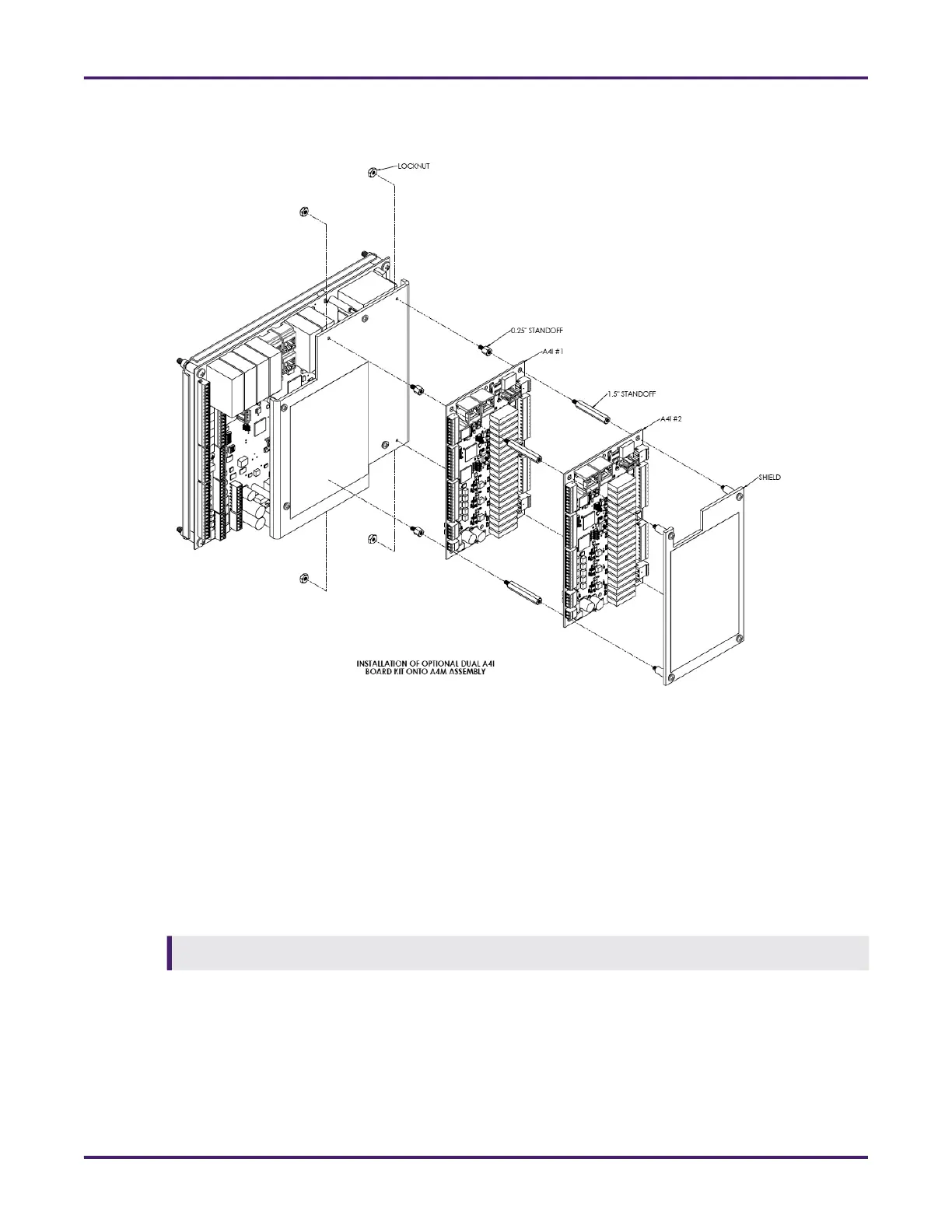
The following drawing shows the installation of the dual A4I board kit.
Complete the following steps to install one or two A4I boards onto the AccuLoad IV’s A4M board:
1. Remove the power supply from the AccuLoad IV.
2. On the ST and QT models, remove the cover bolts. On the N4 or SA models, loosen the latches to
open the door.
3. Remove the four captive screws from the A4M board’s polycarbonate shield using a Phillips head
screwdriver.
4. Remove the captive mounting fastener from the A4M board that is closest to AC input terminal block
TBE1.
5. Install the kit’s four 0.25-inch hex standoffs and nylon insert locknuts onto the A4Ms board’s polycar-
bonate shield.
6. Re-install the A4M board’s shield on the A4M board.
7. Align the 0.25-inch standoffs on the A4M board with the first A4I board (A4I #1). The Ethernet jacks on
the A4I board should be near the Ethernet jacks on the A4M board.
8. On the first A4I board, ensure that DIP switch S1-2 is OFF to designate it as A4I #1.
Due to the risk of cross-threading standoff, remove the captive mounting fastener by hand.
Figure 48: Dual A4I Boards on A4M Board