TP8-96 VIDEO - Installer Manual Bus analysis
8-1
Permits the constant control of theRS485 serial bus where the devices which composed the system are connected.
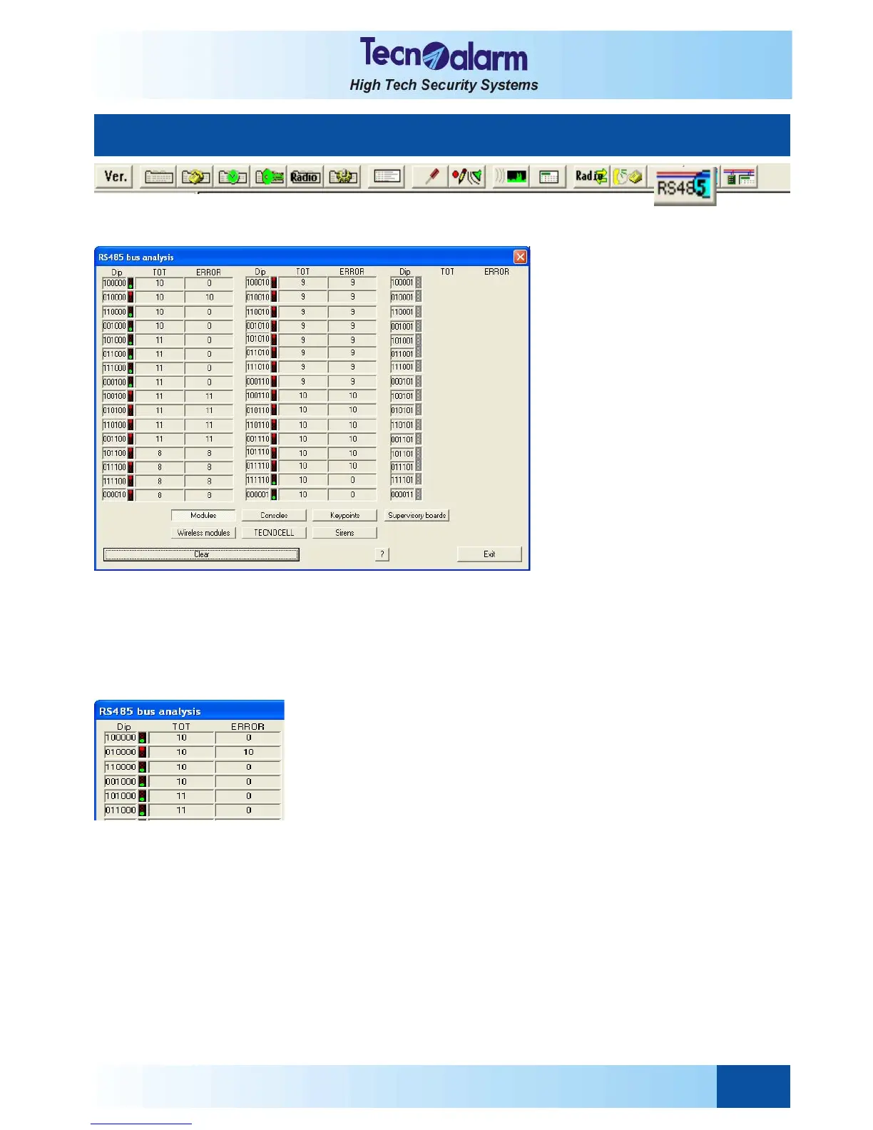
By clicking on the above icon, on the screen is viewed :
The RS485 bus analysis table permits the communication monitoring in order to verify coherence and exactitude of the
datas.
The RS485 bus analysis table permits:
z Viewing of the device addresses
z Viewing of the total counter (TOT) and of the error counters (ERROR)
z Signaling of the communication errors
z Selection of the group to be controlled
DIP
Permits viewing of the device addresses.
TOT
Each communication is analized, totalized and recorded by the TOT total
counter.
ERROR
Each communication considered invalid is recorded, therefore totalizes, into the
ERROR counter (i.e. communication errors).
SIGNALING
The RS485 serial bus analysis connects the TOT and the ERROR counters in
order to determine the data communication reliability between CPU and devices;
it calculates the percentage of errors and classify it using the signaling of a
traffic light. Signaling are the following:
Off signal = peripheral absent, connection absent or permanently
excluded
Green signal = reliable datas, i.e. insignificant error (less than 1%)
Yellow signal = percentage of error from 1 to 3%, i.e. negligible
Red signal = percentage of error highter than 3%, i.e. critical.
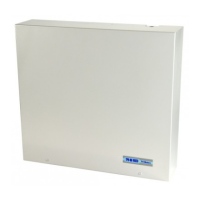
According to the beside example, the peripheral with the address 1 is
present on the installation and signals none error. Therefore the signal is green.
By contrast, the peripheral with the address 01 is not present on the
installation so the number of errors is equal to the number of communications.
As a result, the signal is red.
8. RS485 SERIAL BUS ANALYSIS


 To Next Page