Performance Characteristics
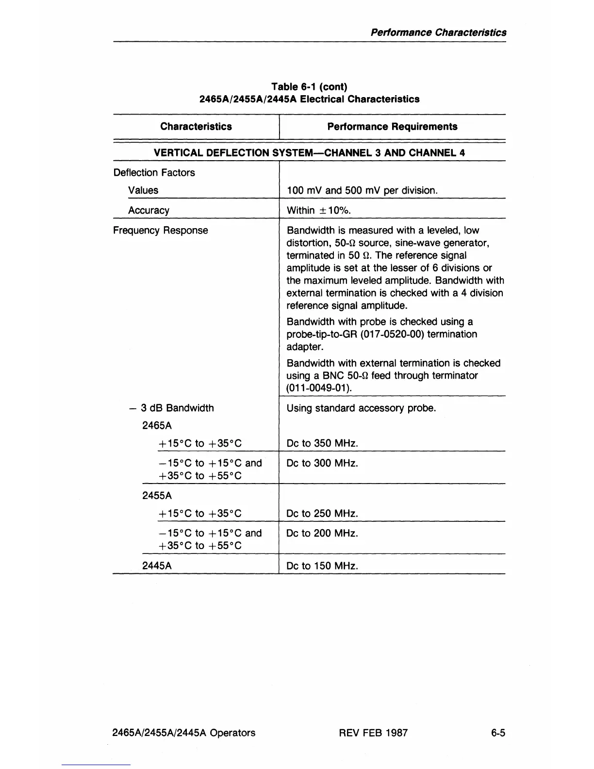
Table 6-1 (cont)
2465A/2455A/2445A Electrical Characteristics
Characteristics Performance Requirements
VERTICAL DEFLECTION
SYSTEM-CHANNEL
3 AND CHANNEL 4
Deflection Factors
Values 100 mV and 500 mV per division.
Accuracy Within
± 10%.
Frequency Response Bandwidth
is
measured with a leveled, low
distortion, 50-n source, sine-wave generator,
terminated
in
50 n. The reference signal
amplitude is set at the lesser of 6 divisions or
the maximum
leveled amplitude. Bandwidth with
external termination is checked with a 4 division
reference signal amplitude.
Bandwidth with probe is checked using a
probe-tip-to-GR
(017-0520-00) termination
adapter.
Bandwidth with external termination
is
checked
using a BNC
50-n feed through terminator
(011-0049-01
).
- 3 dB Bandwidth
Using standard accessory probe.
2465A
+15°C
to
+35°C
Dc
to 350 MHz.
-15°C
to
+15°C
and
Dc
to 300 MHz.
+35°C
to
+55°C
2455A
+15°C
to
+35°C
Dc
to
250 MHz.
-15°C
to
+15°C
and
Dc
to 200 MHz.
+35°C
to
+55°C
2445A Dc
to
150 MHz.
2465A/2455A/2445A Operators
REV
FEB
1987
6-5