Performance Characteristics
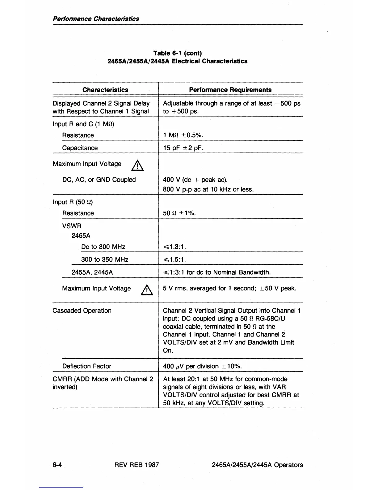
Table 6-1 (cont)
2465A/2455A/2445A
Electrical Characteristics
Characteristics Performance Requirements
Displayed Channel 2 Signal Delay Adjustable through a range of at least - 500 ps
with Respect to
Channel 1 Signal
to
+500
ps.
Input
Rand
C
(1
Mrl)
Resistance 1 Mrl
±0.5%.
Capacitance 15 pF
±2
pF.
Maximum Input Voltage
A
DC,
AC, or GND Coupled
400
V (dc + peak
ac).
800 V
pop
ac at
10kHz
or less.
Input R
(50 rl)
Resistance
50 rl
±1%.
VSWR
2465A
Dc to
300 MHz
~1.3:1.
300 to 350 MHz
~1.5:1.
2455A, 2445A
~
1 :3: 1 for dc to Nominal Bandwidth.
Maximum Input Voltage
A
5 V rms, averaged for 1 second; ± 50 V peak.
Cascaded Operation
Channel 2 Vertical Signal Output into
Channell
input;
DC
coupled using a 50 rl RG-58C/U
coaxial cable, terminated
in
50 rl at the
Channel 1 input. Channel 1 and Channel 2
VOL TS/DIV set at 2 mV and Bandwidth Limit
On.
Deflection Factor 400
,N
per division ± 10%.
CMRR (ADD Mode with Channel 2
At
least 20:1 at 50 MHz for common-mode
inverted) signals
of
eight divisions or less, with V AR
VOL TS/DIV control adjusted for best CMRR at
50 kHz, at any VOL TS/DIV setting.
6-4 REV REB 1987 2465A/2455A/2445A Operators

 Loading...


