Performance Characteristics
Table
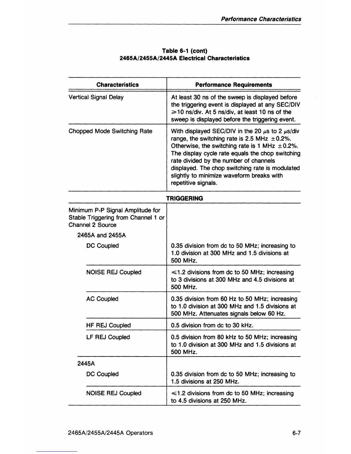
6-1
(cont)
2465A/2455A/2445A
Electrical Characteristics
Characteristics
Vertical Signal Delay
Chopped Mode Switching Rate
Minimum
Pop
Signal Amplitude for
Stable Triggering from Channel 1 or
Channel 2 Source
2465A and 2455A
DC
Coupled
NOISE
REJ
Coupled
AC Coupled
HF
REJ
Coupled
LF
REJ
Coupled
2445A
DC
Coupled
NOISE
REJ
Coupled
2465A/2455A/2445A Operators
Performance Requirements
At
least 30 ns of the sweep
is
displayed before
the triggering event
is
displayed at any SEC/DIV
;;;.10
ns/div.
At
5 ns/div, at least 10 ns
of
the
sweep is
displayed before the triggering event.
With
displayed SEC/DIV
in
the 20
p,S
to
2
p,s/div
range, the switching rate
is
2.5 MHz ± 0.2%.
Otherwise, the switching rate is 1 MHz
± 0.2%.
The
display cycle rate equals the chop switching
rate divided by the number of
channels
displayed.
The chop switching rate is modulated
slightly
to
minimize waveform breaks with
repetitive
signals.
TRIGGERING
0.35 division from dc
to
50 MHz; increasing
to
1.0 division at 300 MHz and 1.5 divisions at
500 MHz.
~1.2
divisions from dc
to
50 MHz; increasing
to
3 divisions at 300 MHz and 4.5 divisions at
500 MHz.
0.35 division from
60 Hz to 50 MHz; increasing
to
1.0 division at 300 MHz and 1.5 divisions at
500 MHz. Attenuates signals below 60 Hz.
0.5 division from dc
to
30 kHz.
0.5 division from 80 kHz
to
50 MHz; increasing
to
1.0 division at 300 MHz and 1.5 divisions at
500 MHz.
0.35 division from dc
to
50 MHz; increasing to
1.5 divisions at
250 MHz.
~1.2
divisions from dc
to
50 MHz; increasing
to
4.5 divisions at 250 MHz.
6-7