Performance Characteristics
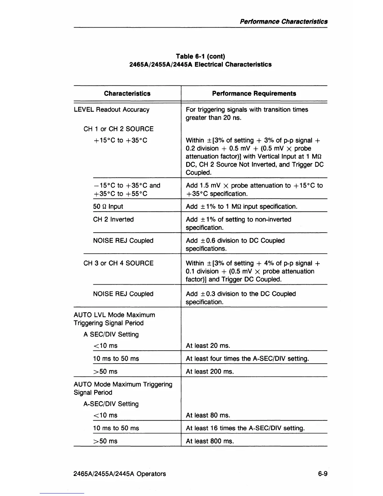
Table 6-1 (cont)
2465A/2455A/2445A
Electrical Characteristics
Characteristics
Performance Requirements
LEVEL Readout Accuracy For triggering signals with transition times
greater than
20
ns.
CH
1 or
CH
2 SOURCE
+15°C
to
+35°C
Within ± [3% of setting + 3% of
pop
signal +
0.2 division + 0.5
mV
+ (0.5
mV
X probe
attenuation factor)] with
Vertical Input at 1 Mf!
DC,
CH
2 Source Not Inverted,
and
Trigger
DC
Coupled.
-15°C
to
+35°C
and
Add 1.5
mV X probe attenuation to + 15 ° C to
+35°C
to
+55°C
+35°C
specification.
50
f! Input
Add ± 1 % to 1 Mf! input specification.
CH
2 Inverted Add ± 1 % of setting to non-inverted
specification.
NOISE
REJ
Coupled Add ± 0.6 division to
DC
Coupled
specifications.
CH
3 or
CH
4 SOURCE Within ± [3% of setting + 4% of
pop
signal +
0.1
division + (0.5
mV
X probe attenuation
factor)) and Trigger
DC
Coupled.
NOISE
REJ
Coupled Add ± 0.3 division to the
DC
Coupled
specification.
AUTO LVL Mode Maximum
Triggering
Signal Period
A
SEC/DIV Setting
<10
ms
At least 20
ms.
10 ms to
50
ms At least four times the A-SEC/DIV setting.
>50
ms
At least 200
ms.
AUTO Mode Maximum Triggering
Signal Period
A-SEC/DIV Setting
<10
ms
At least 80
ms.
10 ms to
50
ms At least 16 times the A-SEC/DIV setting.
>50
ms
At least 800
ms.
2465A/2455A/2445A Operators 6-9