Performance Conditions
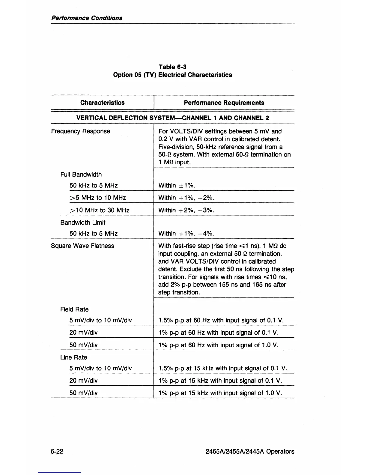
Table 6-3
Option 05 (TV) Electrical Characteristics
Characteristics Performance Requirements
VERTICAL DEFLECTION
SYSTEM-CHANNEL
1
AND
CHANNEL 2
Frequency Response For
VOL TS/DIV settings between 5
mV
and
0.2 V with VAR control
in
calibrated detent.
Five-division, 50-kHz reference signal from a
50-0 system. With external 50-0 termination on
1
MO
input.
Full
Bandwidth
50 kHz to 5 MHz Within
±1%.
>5
MHz to 10 MHz
Within
+1%,
-2%.
>10
MHz to 30 MHz Within
+2%,
-3%.
Bandwidth Limit
50 kHz to 5 MHz Within
+1%,
-4%.
Square Wave Flatness With fast-rise step (rise time
..;;1
ns),
1
MO
dc
input coupling,
an
external
50
0 termination,
and VAR VOLTS/DIV control
in
calibrated
detent. Exclude the first 50 ns following the step
transition. For signals with rise times ..;;10 ns,
add 2%
pop
between 155 ns and 165 ns after
step transition.
Field
Rate
5 mV/div to 10 mV/div 1.5%
pop
at
60
Hz with input signal of
0.1
V.
20
mV/div 1 %
pop
at 60
Hz
with input signal
of
0.1
V.
50
mV/div 1%
pop
at 60
Hz
with input signal
of
1.0
V.
Line Rate
5 mV/div to 10 mV/div
1.5%
pop
at 15 kHz with input signal
of
0.1
V.
20
mV/div
1%
pop
at 15 kHz with input signal
of
0.1
V.
50
mV/div
1 %
pop
at 15 kHz with input signal
of
1.0
V.
6-22 2465A/2455A/2445A Operators