Adjustments—455/A2/B2
C. HORIZONTAL MODULE
Equipment Required
1. Time-Mark Generator
5. 50 £2 Termination
2. Sine-Wave Generator 6. Low-Capacitance Screwdriver
3. Amplitude Calibrator 7. Screwdriver
4. 50 £2 Cable
Preset front panel controls as follows:
NOTE
Do not preset internal controls.
Crt
INTENSITY Midrange
Horizontal
HORIZ DISPLAY A INTEN
TRIG MODE
AUTO
X10MAG out (off)
A COUPLING
AC
A SOURCE
NORM
ATIM E/DIV
1 ms
B TIME/DIV 5 ps
VARTIM E/DIV Calibrated (detent)
position
B SOURCE STARTS AFTER
DELAY
Set all other controls as desired.
The oscilloscope should produce a baseline trace with an
intensified portion when the controls are set as above. Ad
just INTENSITY and FOCUS controls as needed to main
tain a well-defined display while making adjustments.
Cl. SWEEP START-STOP
a. Connect 1 ms markers from time-mark generator to
vertical input via 50 £2 cable and 50 £2 termination.
b. Set DELAY TIME POS control to 1-00. Center
display.
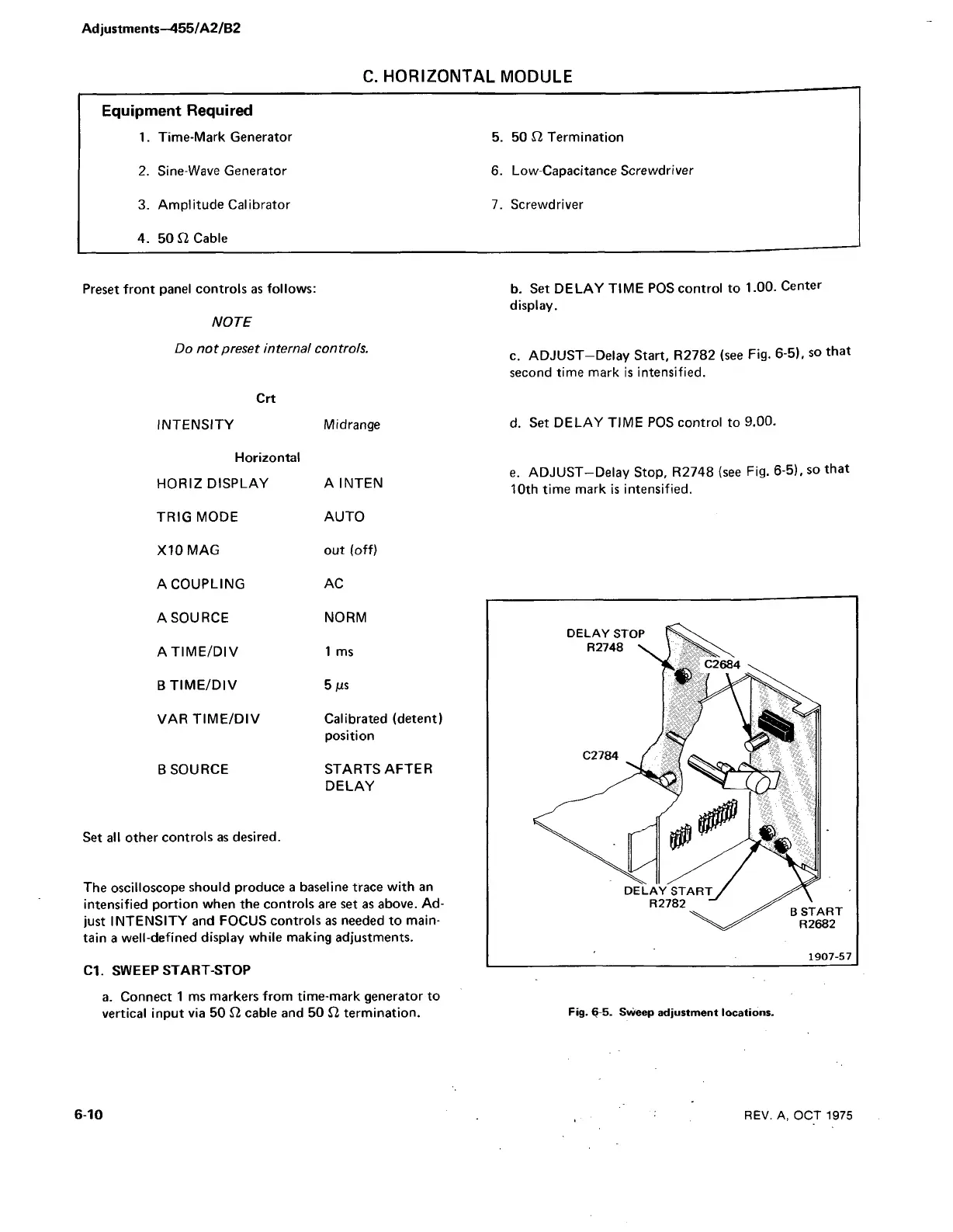
c. ADJUST-Delay Start, R2782 (see Fig. 6-5), so that
second time mark is intensified.
d. Set DELAY TIME POS control to 9.00.
e. ADJUST-Delay Stop, R2748 (see Fig. 6-5), so that
10th time mark is intensified.
Fig. 6 5. Sweep adjustment locations.
6 10 REV. A, OCT 1975