Adjustments—455/A2/B2
c. Center display with horizontal POSITION.
d. Set X10 MAG pushbutton in (on).
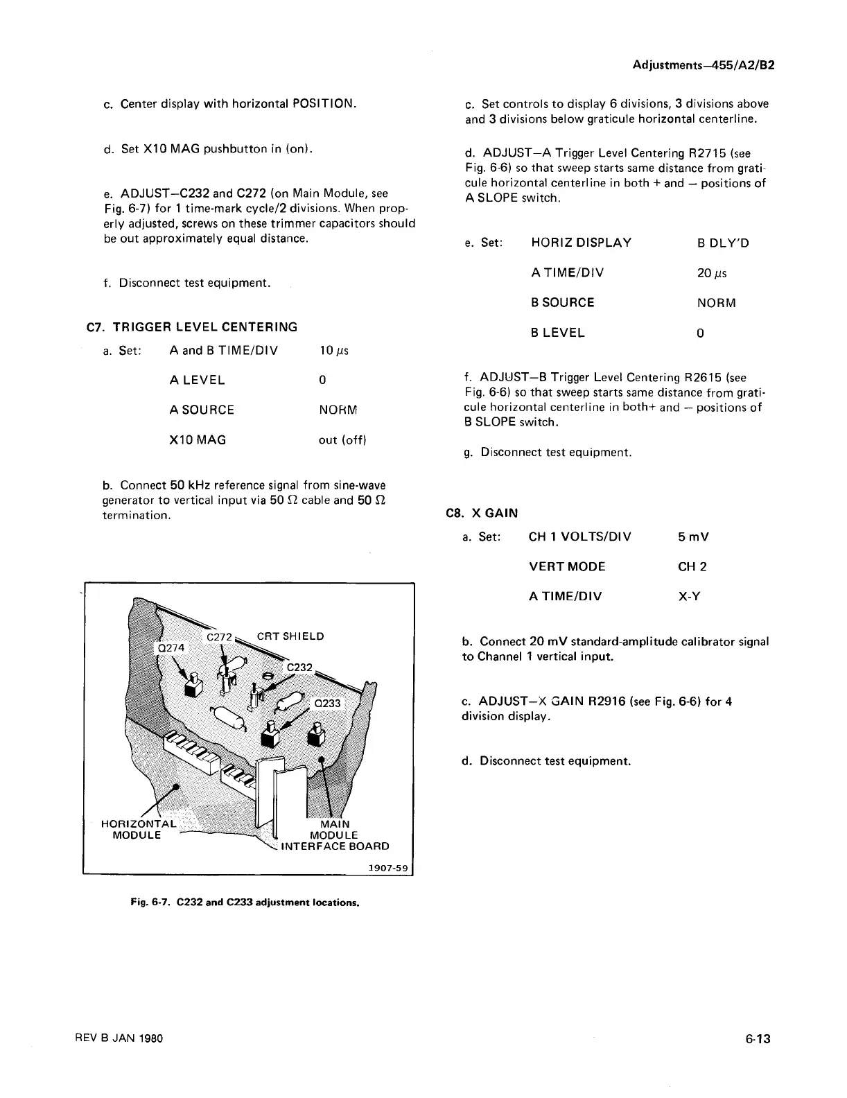
e. ADJUST—C232 and C272 (on Main Module, see
Fig. 6-7) for 1 time-mark cycle/2 divisions. When prop
erly adjusted, screws on these trimmer capacitors should
be out approximately equal distance.
f. Disconnect test equipment.
C7. TRIGGER LEVEL CENTERING
a. Set: A and B TIME/DIV 10jus
A LEVEL 0
A SOURCE NORM
X10MAG out (off)
c. Set controls to display 6 divisions, 3 divisions above
and 3 divisions below graticule horizontal centerline.
d. ADJUST—A Trigger Level Centering R2715 (see
Fig. 6-6) so that sweep starts same distance from grati
cule horizontal centerline in both + and — positions of
A SLOPE switch.
e. Set: HORIZ DISPLAY B DLY'D
ATIM E/DIV 20 ^s
BSOURCE NORM
B LEVEL 0
f. ADJUST—B Trigger Level Centering R2615 (see
Fig. 6-6) so that sweep starts same distance from grati
cule horizontal centerline in both+ and — positions of
B SLOPE switch.
g. Disconnect test equipment.
b. Connect 50 kHz reference signal from sine-wave
generator to vertical input via 50 £2 cable and 50 £2
termination.
C8. X GAIN
a. Set: CH 1 VOLTS/DIV 5 mV
VERT MODE CH 2
AT IM E/D IV X-Y
b. Connect 20 mV standard-amplitude calibrator signal
to Channel 1 vertical input.
c. ADJUST-X GAIN R2916 (see Fig. 6-6) for 4
division display.
d. Disconnect test equipment.
Fig. 6-7. C232 and C233 adjustment locations.
REV B JAN 1980
6-13