Operating Instructions—455/A2/B2
BASIC APPLICATIONS AND MEASUREMENTS
Peak-to-Peak Amplitude Measurements
To measure the amplitude of a signal, multiply the vertical
deflection (in divisions) by the VOLTS/DIV Switch setting.
Example:
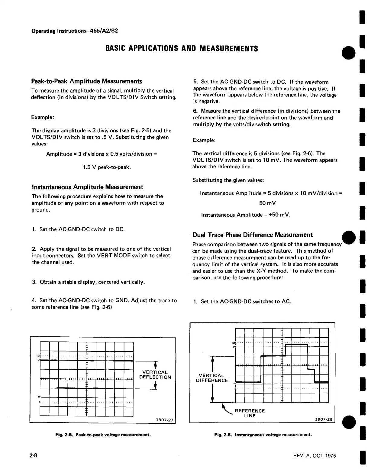
The display amplitude is 3 divisions (see Fig. 2-5) and the
VOLTS/DIV switch is set to .5 V. Substituting the given
values:
Amplitude = 3 divisions x 0.5 volts/division =
1.5 V peak-to-peak.
Instantaneous Amplitude Measurement
The following procedure explains how to measure the
amplitude of any point on a waveform with respect to
ground.
1. Set the AC-GND-DC switch to DC.
2. Apply the signal to be measured to one of the vertical
input connectors. Set the VERT MODE switch to select
the channel used.
3. Obtain a stable display, centered vertically.
4. Set the AC-GND-DC switch to GND. Adjust the trace to
some reference line (see Fig. 2-6).
5. Set the AC-GND-DC switch to DC. If the waveform
appears above the reference line, the voltage is positive. If
the waveform appears below the reference line, the voltage
is negative.
6. Measure the vertical difference (in divisions) between the
reference line and the desired point on the waveform and
multiply by the volts/div switch setting.
Example:
The vertical difference is 5 divisions (see Fig. 2-6). The
VOLTS/DIV switch is set to 10 mV. The waveform appears
above the reference line.
Substituting the given values:
Instantaneous Amplitude = 5 divisions x 10 mV/division =
50 mV
Instantaneous Amplitude = +50 mV.
Dual Trace Phase Difference Measurement
Phase comparison between two signals of the same frequency
can be made using the dual-trace feature. This method of
phase difference measurement can be used up to the fre
quency lim it of the vertical system. It is also more accurate
and easier to use than the X-Y method. To make the com
parison, use the following procedure:
1. Set the AC-GND-DC switches to AC.
VERTICAL
DEFLECTION
1
1907-27
Fig. 2-5. Peak-to-peak voltage measurement.
Fig. 2-6. Instantaneous voltage measurement.