Maintenance—455/A2/B2
COMPONENT REMOVAL AND REPLACEMENT
WARNING I
To prevent electrical shocK or damage to instru
ment, always disconnect the instrument from
the power source before replacing components.
Rear Panel Assembly Removal
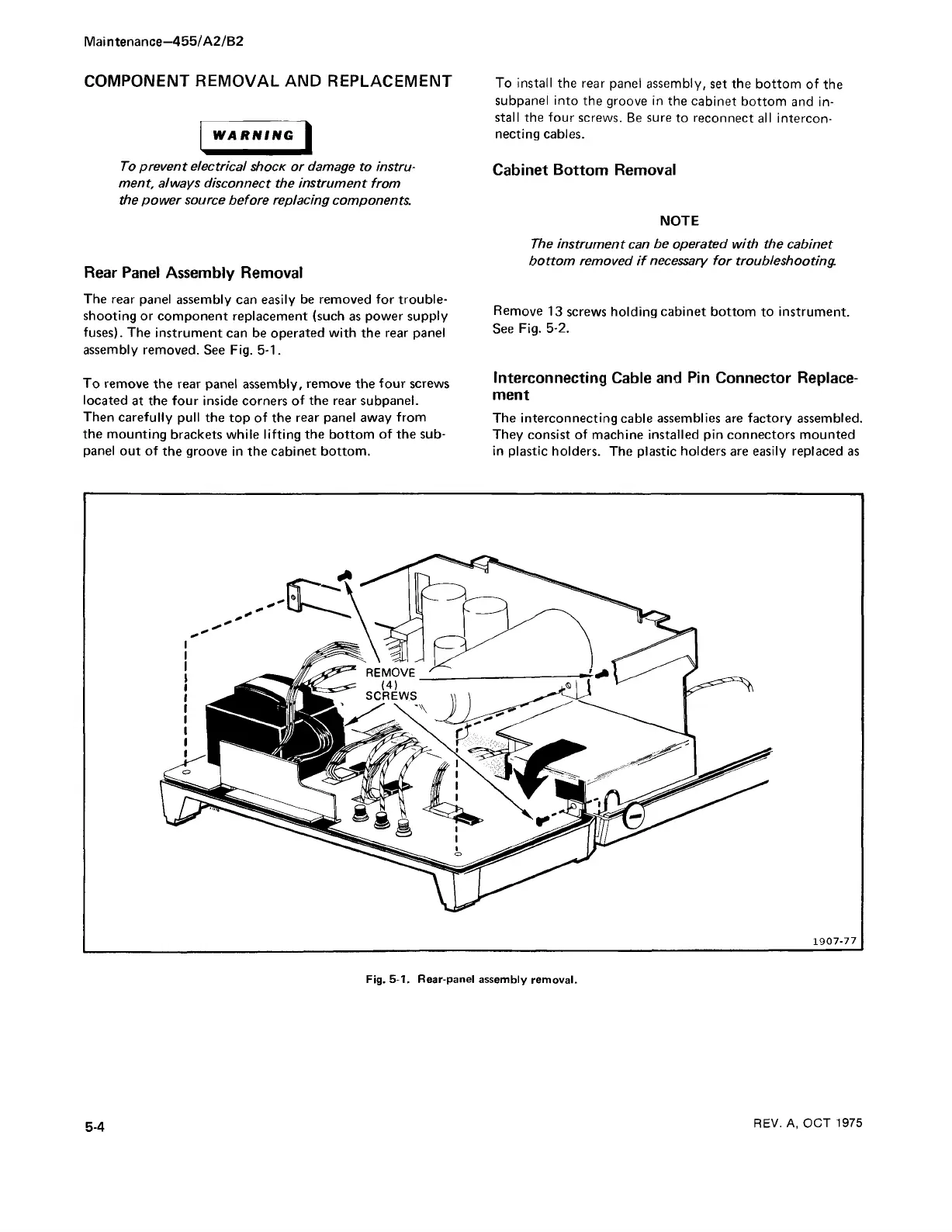
The rear panel assembly can easily be removed for trouble
shooting or component replacement (such as power supply
fuses). The instrument can be operated with the rear panel
assembly removed. See Fig. 5-1.
To remove the rear panel assembly, remove the four screws
located at the four inside corners of the rear subpanel.
Then carefully pull the top of the rear panel away from
the mounting brackets while lifting the bottom of the sub
panel out of the groove in the cabinet bottom.
To install the rear panel assembly, set the bottom of the
subpanel into the groove in the cabinet bottom and in
stall the four screws. Be sure to reconnect all intercon
necting cables.
Cabinet Bottom Removal
NOTE
The instrument can be operated with the cabinet
bottom removed if necessary for troubleshooting
Remove 13 screws holding cabinet bottom to instrument.
See Fig. 5-2.
Interconnecting Cable and Pin Connector Replace
ment
The interconnecting cable assemblies are factory assembled.
They consist of machine installed pin connectors mounted
in plastic holders. The plastic holders are easily replaced as
1907-77
Fig. 5-1. Rear-panel assembly removal.
5-4
REV. A, OCT 1975