Maintenance—455/A2/B2
Example: General Radio W 8 MT 3 VM or W10 MT 3 W
Metered Variac Autotransformer.
5. Module Extender Troubleshooting fixture
Description: 18 inch ribbon cable with a module inter
face connector at each end (Tektronix part 067-0757-00).
Purpose: To operate Vertical and Horizontal modules
outside of Main module. Useful for troubleshooting
circuits which are inaccessible with modules installed.
TROUBLESHOOTING TECHNIQUES
This troubleshooting procedure is arranged in an order that
checks the simple trouble possibilities before proceeding
with extensive troubleshooting. The first few checks ensure
proper connection, operation and calibration. If the trouble
is not located by these checks, the remaining steps should
aid in locating the defective component. Replace defective
components using the replacement instructions under
Corrective Maintenance.
Check Control Settings
Incorrect control settings can indicate a trouble that does
not exist. If there is any question about the correct func
tion or operation of any control, see the Operating Informa
tion sections.
Check Associated Equipment
Before proceeding with troubleshooting, check that the
equipment used with this instrument is operating correctly.
Check that the signal is properly connected and that the
interconnecting cables are not defective. Also, check the
power source.
Check Instrument Calibration
Check the calibration of this instrument, or the affected
circuit if the trouble exists in one circuit. The apparent
trouble may only be misadjustment that can be corrected
by calibration. Complete calibration instructions are given
in the Adjustments sections of this manual.
Visual Check
Visually check the portion of the instrument in which the
trouble is located. Many troubles can be located by visual
indications such as unsoldered connections, broken wires,
damaged circuit boards, and damaged components.
Isolate Trouble to a Circuit
Using the troubleshooting chart (Fig. 5-13), isolate trouble
to a particular circuit. The symptom often identifies the
defective circuit. Trouble appearing in more than one cir
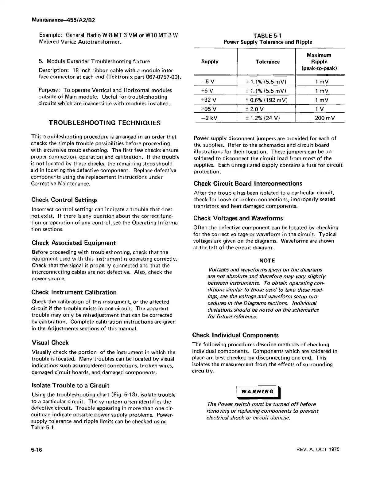
cuit can indicate possible power supply problems. Power-
supply tolerance and ripple limits can be checked using
Table 5-1.
TABLE 5-1
Power Supply Tolerance and Ripple
Supply
Tolerance
Maximum
Ripple
(peak-to-peak)
- 5 V
+ 1.1% (5.5 mV)
1 mV
+5 V
±1.1% (5.5 mV) 1 mV
+32 V
±0.6% (192 mV)
1 mV
+95 V
± 2.0 V
1 V
-2 kV
± 1.2% (24 V)
200 mV
Power supply disconnect jumpers are provided for each of
the supplies. Refer to the schematics and circuit board
illustrations for their location. These jumpers can be un
soldered to disconnect the circuit load from most of the
supplies. Each unregulated supply contains a fuse for circuit
protection.
Check Circuit Board Interconnections
After the trouble has been isolated to a particular circuit,
check for loose or broken connections, improperly seated
transistors and heat damaged components.
Check Voltages and Waveforms
Often the defective component can be located by checking
for the correct voltage or waveform in the circuit. Typical
voltages are given on the diagrams. Waveforms are shown
at the left of the circuit diagram.
NOTE
Voltages and waveforms given on the diagrams
are no t absolute and therefore may vary slightly
between instruments. To obtain operating con
ditions similar to those used to take these read
ings, see the voltage and waveform setup pro
cedures in the Diagrams sections. Individual
deviations should be noted on the schematics
fo r future reference.
Check Individual Components
The following procedures describe methods of checking
individual components. Components which are soldered in
place are best checked by disconnecting one end. This
isolates the measurement from the effects of surrounding
circuitry.
WARNING |
The Power switch must be turned o ff before
removing or replacing components to prevent
electrical shock or circuit damage.
5-16
REV. A, OCT 1975