Circuit Description—455/A2/B2
Horizontal Preamplifier 1C
The Horizontal Preamplifier circuit is contained within a
single 1C, U2900.
The following is a brief description of the function associat
ed with each pin of U2900.
Pin 1. Magnifier registration. This pin is used in con
junction with pin 8 to provide registration between the
normal and magnified sweeps.
Pin 2. Sweep. This pin provides the negative-going
sweep output to the Horizontal Output Amplifier. This
output represents the inputs to pin 9 or 10, except in the
X-V mode when pin 12 is HI, and it represents the input
to pin 11.
Pin 3. Gain. This pin, in conjunction with pin 6, is con
nected to the gain setting circuitry. The X I0 Magnifier
switch is connected to this pin.
Pin 4. —5 volt supply.
Pin 5. Current source. Sets internal current levels.
Pin 6. Gain. See pin 3.
Pin 7. + Sweep. This pin provides the positive-going
sweep output to the Horizontal Output Amplifier.
Pin 8. Magnifier registration. See pin 1.
Pin 9. B Sweep In. Input connection for the B sweep
signal.
Pin 10. A Sweep In. Input connection for the A sweep
signal.
Pin 11. X Signal. Input connection for the X signal
from CH 1 when the A TIME/DIV switch is in the X-Y
position.
Pin 12. X-Y Mode. When this pin is LO (normal sweep
mode), the outputs at pins 2 and 7 represent the inputs
to pin 9 or pin 10.
Pin 13. Frequency compensation. Connects to frequen
cy compensating capacitor.
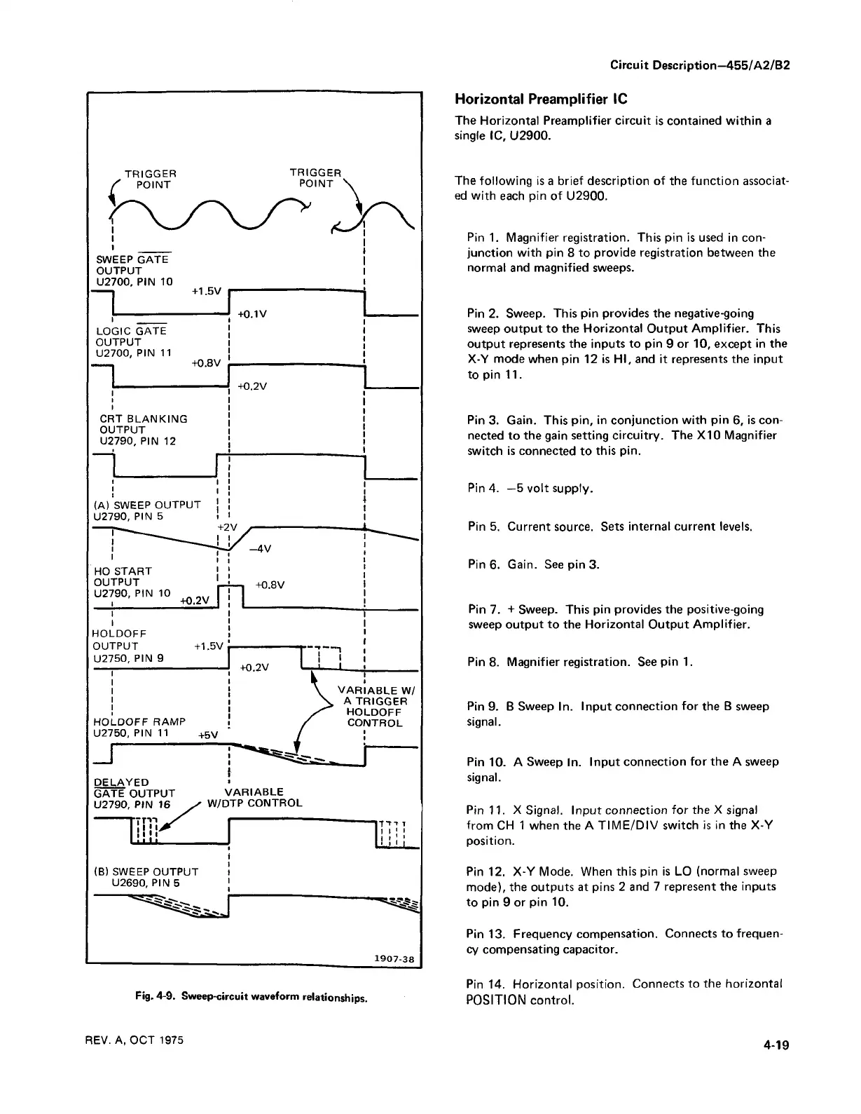
Fig. 4-9. Sweep-circuit waveform
relationships.
9
REV. A, OCT 1975
Pin 14. Horizontal position. Connects to the horizontal
POSITION control.