Circuit Description-455/A2/B2
B Dly'd Sweep Mode
In the B DLY'D mode. Fig. 4-10, the A sweep operates
similarly to the A mode, but the A sweep output at pin
5 of U2790 and the unblanking output at pin 12 of U2790
are disabled.
When the A sweep ramp within U2790 reaches the level set
by the DELAY TIME POS control, pin 14 of U2690 goes
LO to start the B sweep. In the STARTS AFTER DELAY
mode, pin 9 of U2600 is held HI and pin 10 of U2600 is
held LO, allowing the B sweep to start as soon as pin 14 of
U2690 goes LO. The time A sweep takes to reach the level
set by the DELAY TIME POS control represents the time
from the start of A sweep to the start of B sweep. The de
layed time is determined by multiplying the A TIME/DIV
setting by the DELAY TIME POS setting. In all other po
sitions of the B SOURCE switch the B sweep does not start
until a trigger signal occurs at pin 2 of U2600. When the B
sweep starts, a crt unblanking signal is produced at pin 12
of U2690 to unblank the crt. When the B sweep reaches a
predetermined level within U2690, output current at pin 12
drops, unblanking the crt. The B sweep stops running down
and remains negative until reset by the delayed gate pulse
going HI, which occurs when the A sweep terminates.
U2740A and B provide a voltage source for the DELAY
TIME POS circuit.
A Inten Sweep Mode
In the A INTEN mode, both A and B sweeps operate. The
B sweep output at pin 5 of U2690 is disabled as in the A
mode. The B sweep unblanking signal at pin 12 of U2690
adds to the A sweep unblanking signal to intensify the B
sweep time segment of the A sweep display.
+5V
IN
NORM POSITION
1907-37
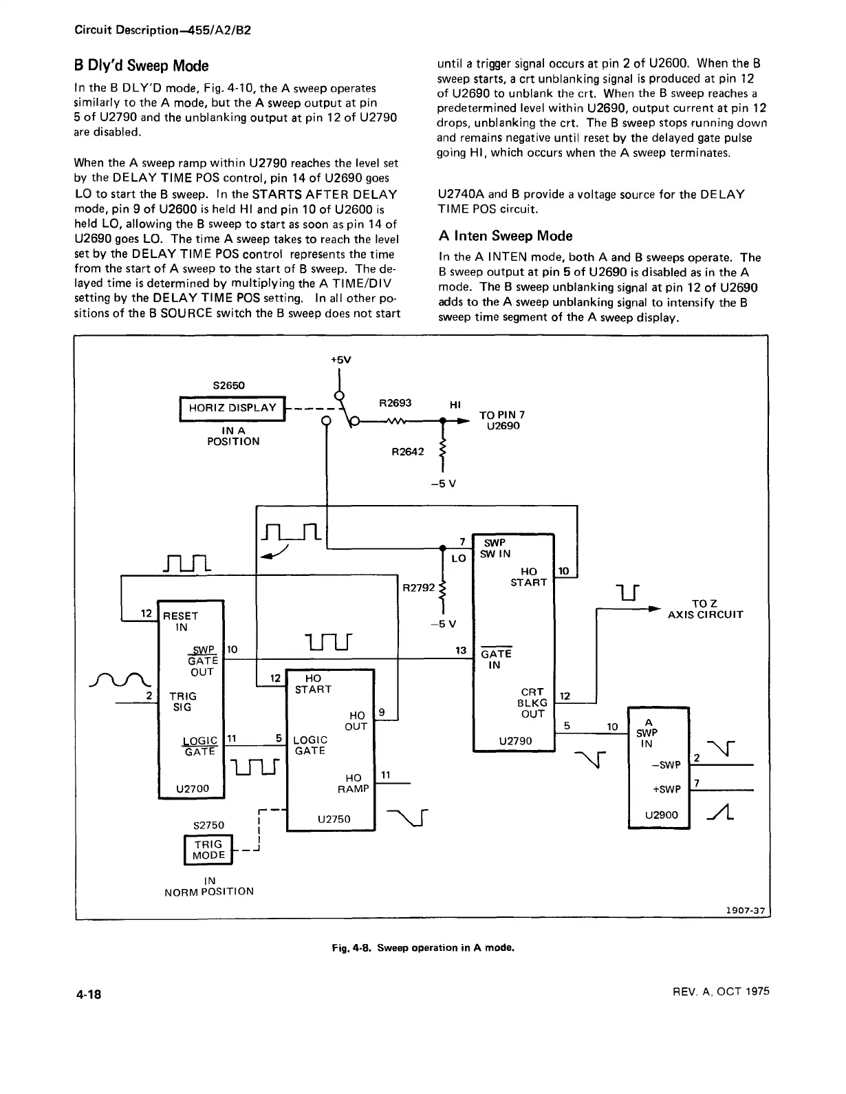
Fig. 4-8. Sweep operation in A mode.
4-18
REV. A, OCT 1975