Instrument Options—455/A2/B2
CIRCUIT DESCRIPTION
Option 7 consists basically of a dc to ac inverter that operates on 12 or.24 volts. The circuit description discusses 24 volt oper
ation unless noted otherwise. Refer to the schematic diagrams for additional details.
The operating frequency of the inverter is approximately 400 Hz.
BLOCK DIAGRAM
(See Fig. 3)
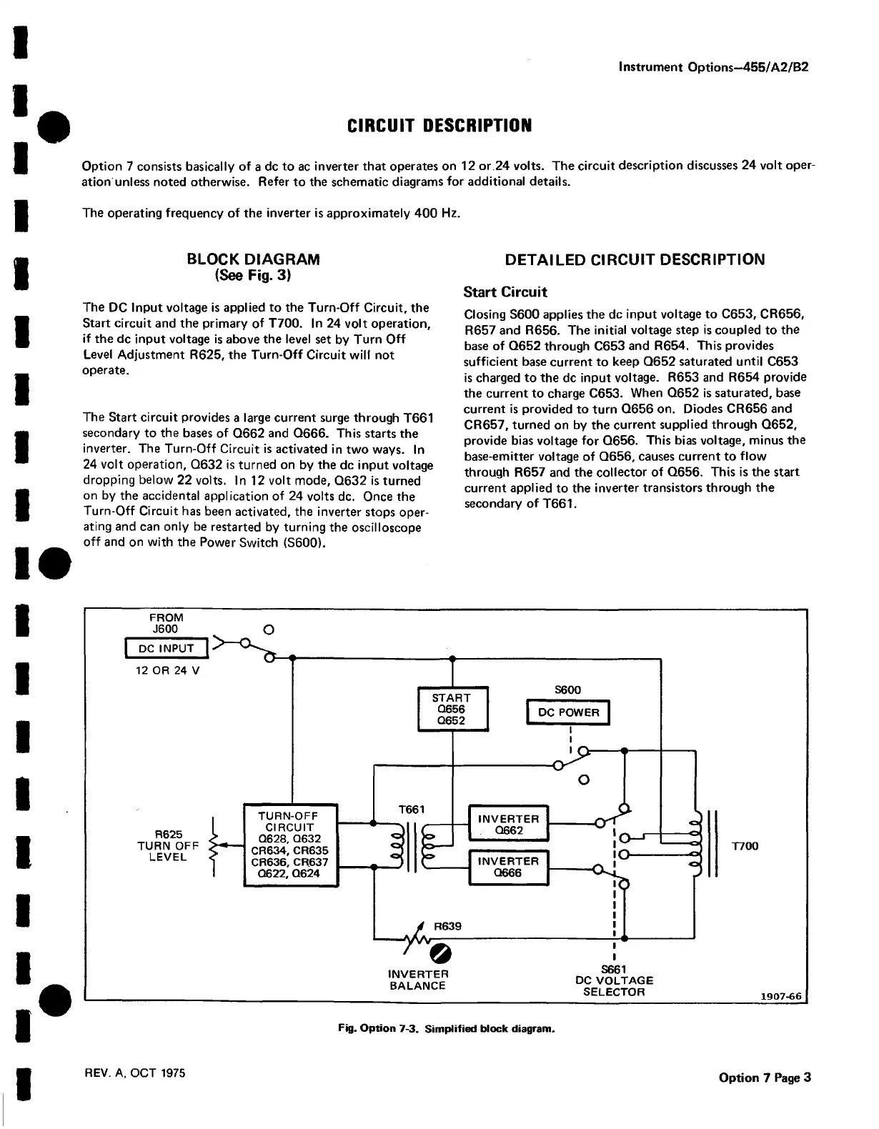
The DC Input voltage is applied to the Turn-Off Circuit, the
Start circuit and the primary of T700. In 24 volt operation,
if the dc input voltage is above the level set by Turn Off
Level Adjustment R625, the Turn-Off Circuit will not
operate.
The Start circuit provides a large current surge through T661
secondary to the bases of Q662 and Q666. This starts the
inverter. The Turn-Off Circuit is activated in two ways. In
24 volt operation, Q632 is turned on by the dc input voltage
dropping below 22 volts. In 12 volt mode, Q632 is turned
on by the accidental application of 24 volts dc. Once the
Turn-Off Circuit has been activated, the inverter stops oper
ating and can only be restarted by turning the oscilloscope
off and on with the Power Switch (S600).
DETAILED CIRCUIT DESCRIPTION
Start Circuit
Closing S600 applies the dc input voltage to C653, CR656,
R657 and R656. The initial voltage step is coupled to the
base of Q652 through C653 and R654. This provides
sufficient base current to keep Q652 saturated until C653
is charged to the dc input voltage. R653 and R654 provide
the current to charge C653. When Q652 is saturated, base
current is provided to turn Q656 on. Diodes CR656 and
CR657, turned on by the current supplied through Q652,
provide bias voltage for Q656. This bias voltage, minus the
base-emitter voltage of Q656, causes current to flow
through R657 and the collector of Q656. This is the start
current applied to the inverter transistors through the
secondary of T661.
FROM
INVERTER
BALANCE
S661
DC VOLTAG E
SELECTOR
T700
1907-66
Fig. Option 7-3. Simplified block diagram.
REV. A, OCT 1975
Option 7 Page 3