Instrument Options—455/A2/B2
The output of the sync-separator circuit is supplied to the
A and B trigger generators via the A COUPLING and B
SOURCE switches. The output of the vertical sync recog
nizer is supplied to the A trigger generator via the A COUPL
ING Switch.
INPUT BUFFER AMPLIFIER
Q2212 is an FET source follower. It provides a high-impe
dance input for isolation and a low-impedance output to
drive the input of the Inverting/Non-Inverting Amplifier.
INVERTING/NON-INVERTING AMPLIFIER
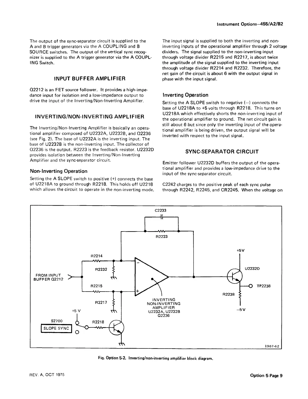
The Inverting/Non-Inverting Amplifier is basically an opera
tional amplifier composed of U2232A, U2232B, and Q2236
(see Fig. 2). The base of U2232A is the inverting input. The
base of U2232B is the non-inverting input. The collector of
Q2236 is the output. R2223 is the feedback resistor. U2232D
provides isolation between the Inverting/Non-Inverting
Amplifier and the sync-separator circuit.
Non-Inverting Operation
Setting the A SLOPE switch to positive (+) connects the base
of U2218A to ground through R2218. This holds off U2218
which allows the circuit to operate in the non-inverting mode.
The input signal is supplied to both the inverting and non
inverting inputs of the operational amplifier through 2 voltage
dividers. The signal supplied to the non-inverting input
through voltage divider R2215 and R2217, is about twice
the amplitude of the signal supplied to the inverting input
through voltage divider R2214 and R2232. Therefore, the
net gain of the circuit is about 6 with the output signal in
phase with the input signal.
Inverting Operation
Setting the A SLOPE switch to negative (—) connects the
base of U2218A to +5 volts through R2218. This turns on
U2218A which effectively shorts the non-inverting input of
the operational amplifier to ground. The net circuit gain is
still about 6 but since only the inverting input of the opera
tional amplifier is being driven, the output signal will be
inverted with respect to the input signal.
SYNC-SEPARATOR CIRCUIT
Emitter follower U2232D buffers the output of the opera
tional amplifier and provides a low-impedance drive to the
input of the sync-separator circuit.
C2242 charges to the positive peak of each sync pulse
through R2242, R2245, and CR2245. When the voltage on
Fig. Option 5-2. Inverting/non-inverting amplifier block diagram.
REV. A, OCT 1975
Option 5 Page 9