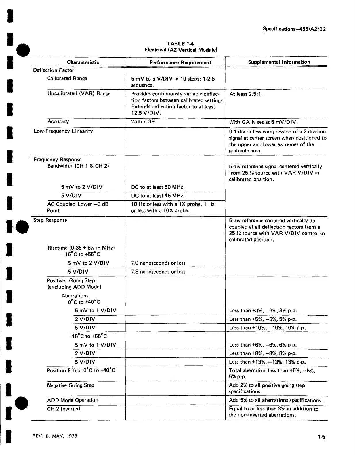
Specifications—455/A2/B2
TABLE 1-4
Electrical (A2 Vertical Module)
Characteristic
Performance Requirement
Supplemental Information
Deflection Factor
Calibrated Range
5 mV to 5 V/D IV in 10 steps: 1-2-5
sequence.
Uncalibrated (VAR) Range
Provides continuously variable deflec
tion factors between calibrated settings.
Extends deflection factor to at least
12.5 V/DIV.
At least 2.5:1.
Accuracy
Within 3%
With GAIN set at 5 mV/DIV.
Low-Frequency Linearity
0.1 div or less compression of a 2 division
signal at center screen when positioned to
the upper and lower extremes of the
graticule area.
Frequency Response
Bandwidth (CH 1 & CH 2)
5 mV to 2 V/DIV
DC to at least 50 MHz.
5-div reference signal centered vertically
from 25 £2 source with VAR V/D IV in
calibrated position.
5 V/DIV DC to at least 45 MHz.
AC Coupled Lower —3 dB
Point
10 Hz or less with a IX probe. 1 Hz
or less with a 10X probe.
Step Response
Risetime (0.35 + bw in MHz)
— 15°C to +55°C
5 mV to 2 V/DIV
7.0 nanoseconds or less
5-div reference centered vertically dc
coupled at all deflection factors from a
25 £2 source with VAR V/DIV control in
calibrated position.
5 V/D IV
7.8 nanoseconds or less
Positive—Going Step
(excluding ADD Mode)
Aberrations
0°C to +40° C
5 mV to 1 V/DIV
Less than +3%, —3%, 3% p-p.
2 V/DIV Less than +5%, —5%, 5% p-p.
5 V/D IV
Less than +10%, —10%, 10% p-p.
—15°C to +55°C
5 mV to 1 V/DIV Less than +6%, —6%, 6% p-p.
2 V/DIV Less than +8%, —8%, 8% p-p.
5 V/DIV
Less than +13%, -13%, 13% p-p.
Position Effect 0°C to +40°C
Total aberration less than +5%, —5%,
5% p-p.
Negative Going Step
Add 2% to all positive going step
specifications.
ADD Mode Operation
Add 5% to all aberrations specifications.
CH 2 Inverted Equal to or less than 3% in addition to
the non-inverted aberrations.
REV. B, MAY, 1978
1-5