Operating Instructions—455/A2/B2
6
BEAM FINDER—Used to locate an off-screen display.
When pushed, a compressed display is visible within
the graticule area independent of display position
intensity setting, or applied signals.
To locate an off-screen display, use the following procedure:
1. Set the vertical POSITION control and the INTENSITY
control to midrange and rotate the horizontal POSITION
control clockwise.
2. If a display or dot still is not visible, press the BEAM
FINDER button and hold it in. This causes a compressed
display or dot to appear.
a. The appearance of a dot indicates inadequate
triggering. Set the TRIG MODE switch to AUTO to
obtain a reference display. Center the reference dis
play with the vertical and horizontal POSITION
controls. Release the BEAM FINDER button and
adjust the trigger controls for a stable display.
b. If a compressed display appears, adjust the VOLTS/
DIV switch and the horizontal and vertical POSITION
controls to center the display. Release the BEAM
FINDER button and adjust the trigger controls for a
stable display.
[ 7 | CALIBRATOR—Provides a 300 mV, approximately
1 kHz, square-wave output for compensating voltage
probes and checking vertical gain. The CALIBRATOR
output is not intended for verifying timing accuracy.
NOTE
The CALIBRA TOR output can also be used to
calibrate current probes by attaching a current
loop to the output terminals. To make a plug
in current loop, order Tektronix Part 012-0259-
00 and m odify it by replacing the 50 £2 resistor
(inside) with a bare wire. A current loop also
can be made from 5 turns o f insulated wire.
8
SCALE ILLUM—Controls graticule illumination.
Rear Panel (Fig. 2-2)
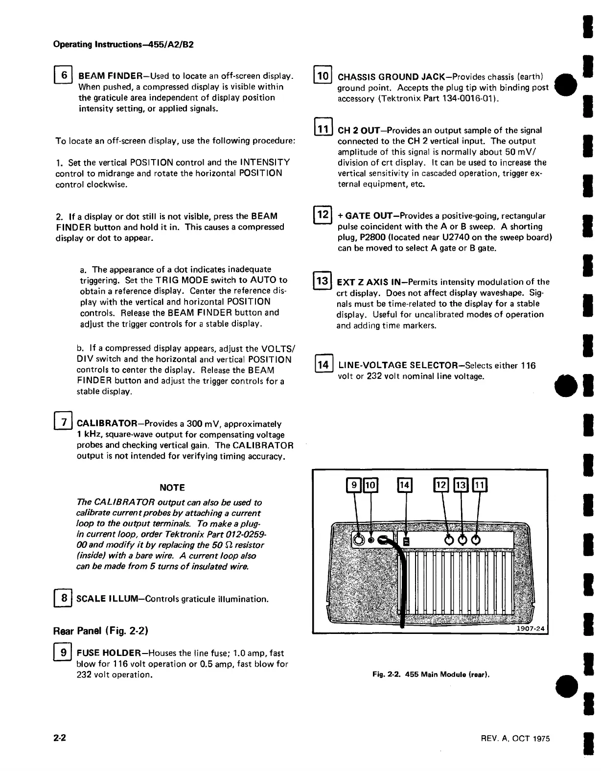
9
FUSE HOLDER—Houses the line fuse; 1.0 amp, fast
blow for 116 volt operation or 0.5 amp, fast blow for
232 volt operation.
10
CHASSIS GROUND JACK—Provides chassis (earth)
ground point. Accepts the plug tip with binding post
accessory {Tektronix Part 134-0016-01).
11 CH 2 OUT—Provides an output sample of the signal
connected to the CH 2 vertical input. The output
amplitude of this signal is normally about 50 mV/
division of crt display. It can be used to increase the
vertical sensitivity in cascaded operation, trigger ex
ternal equipment, etc.
12
+ GATE OUT—Provides a positive-going, rectangular
pulse coincident with the A or B sweep. A shorting
plug, P2800 (located near U2740 on the sweep board)
can be moved to select A gate or B gate.
13
EXT Z AXIS IN—Permits intensity modulation of the
crt display. Does not affect display waveshape. Sig
nals must be time-related to the display for a stable
display. Useful for uncalibrated modes of operation
and adding time markers.
14
LINE-VOLTAGE SELECTOR-Selects either 116
volt or 232 volt nominal line voltage.
Fig. 2-2. 455 Main Module (rear).
2-2
REV. A, OCT 1975