Operating Instructions—455/A2/B2
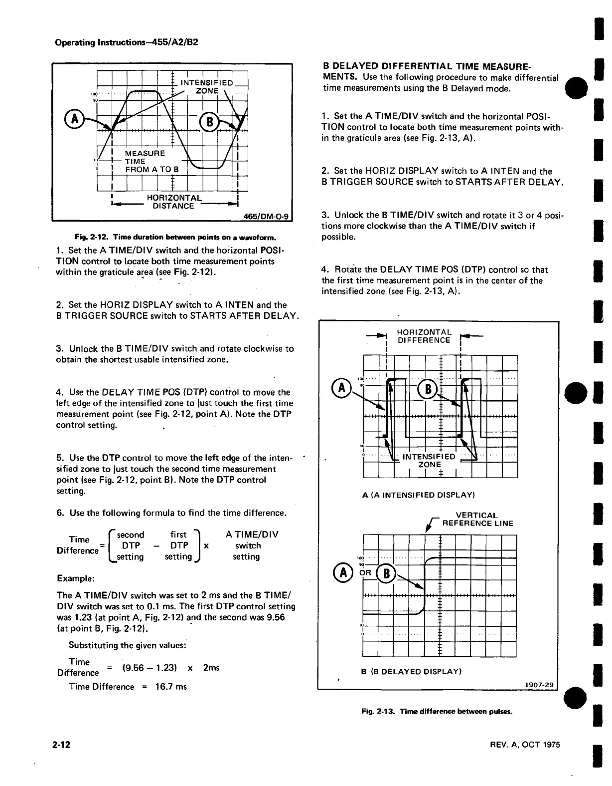
Fig. 2-12. Time duration between points on a waveform.
1. Set the A TIM E/DIV switch and the horizontal POSI
TION control to Locate both time measurement points
within the graticule area (see Fig. 2-12).
2. Set the HORIZ DISPLAY switch to A INTEN and the
B TRIGGER SOURCE switch to STARTS AFTER DELAY
3. Unlock the B TIME/DIV switch and rotate clockwise to
obtain the shortest usable intensified zone.
4. Use the DELAY TIME POS (DTP) control to move the
left edge of the intensified zone to just touch the first time
measurement point (see Fig. 2-12, point A). Note the DTP
control setting.
5. Use the DTP control to move the left edge of the inten
sified zone to just touch the second time measurement
point (see Fig. 2-12, point B). Note the DTP control
setting.
6. Use the following formula to find the time difference.
Time
Difference
C second
DTP
^setting
first
DTP
setting
x
A TIME/DIV
switch
setting
Example:
The A TIME/DIV switch was set to 2 ms and the B TIME/
Dl V switch was set to 0.1 ms. The first DTP control setting
was 1.23 (at point A, Fig. 2-12) and the second was 9.56
(at point B, Fig. 2-12).
Substituting the given values:
Time
Difference
(9.56 - 1.23) x 2ms
Time Difference = 16.7 ms
B DELAYED DIFFERENTIAL TIME MEASURE
MENTS. Use the following procedure to make differential
time measurements using the B Delayed mode.
1. Set the A TIME/DIV switch and the horizontal POSI
TION control to locate both time measurement points with
in the graticule area (see Fig. 2-13, A).
2. Set the HORIZ DISPLAY switch to A INTEN and the
B TRIGGER SOURCE switch to STARTS AFTER DELAY.
3. Unlock the B TIM E/DIV switch and rotate it 3 or 4 posi
tions more clockwise than the A TIME/DIV switch if
possible.
4. Rotate the DELAY TIME POS (DTP) control so that
the first time measurement point is in the center of the
intensified zone (see Fig. 2-13, A).
HORIZONTAL
DIFFERENCE
A (A INTENSIFIED DISPLAY)
VERTICAL
f REFERENCE LINE
1
o • • • •
p j
3 k
r
n\
o - - - -
B (B DELAYED DISPLAY)
1907-29
Fig. 2-13. Time difference between pulses.
2-12
REV. A, OCT 1975