Performance Check—455/A2/B2
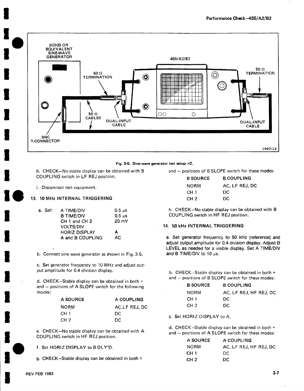
SG503 OR
EQUIVALENT
SINE-WAVE
GENERATOR 455/A 2/B2
BNC
T-CONNECTOR
1907-12
Fig. 3-5. Sine-wave generator test setup #2.
h. CHECK—No stable display can be obtained with B
COUPLING switch in LF REJ position.
i. Disconnect test equipment.
13. 10 MHz INTERNAL TRIGGERING
and — positions of B SLOPE switch for these modes
B SOURCE B COUPLING
NORM AC, LF REJ, DC
CH 1 DC
CH 2 DC
A TIME/DIV
0.5 /us
B TIME/DIV
0.5 /xs
CH 1 and CH 2 20 mV
VOLTS/DIV
HORIZ DISPLAY
A
A and B COUPLING
AC
b. Connect sine wave generator as shown in Fig. 3-5.
c. Set generator frequency to 10 MHz and adjust out
put amplitude for 0.4 division display.
d. CHECK—Stable display can be obtained in both +
and — positions of A SLOPE switch for the following
modes:
A SOURCE A COUPLING
NORM AC,LF REJ, DC
CH 1 DC
CH 2 DC
e. CHECK—No stable display can be obtained with A
COUPLING switch in HF REJ position.
f. Set HORIZ DISPLAY to B DLY'D.
g. CHECK—Stable display can be obtained in both +
h. CHECK—No stable display can be obtained with B
COUPLING switch in HF REJ position.
14. 50 kHz INTERNAL TRIGGERING
a. Set generator frequency to 50 kHz (reference) and
adjust output amplitude for 0.4 division display. Adjust B
LEVEL as needed for a visible display. Set A TIME/DIV
and B TIME/DIV to 10 ns.
b. CHECK—Stable display can be obtained in both +
and — positions of B SLOPE switch for these modes:
B SOURCE B COUPLING
NORM AC, LF REJ, HF REJ, DC
CH 1 DC
CH 2 DC
c. Set HORIZ DISPLAY to A.
d. CHECK—Stable display can be obtained in both +
and — positions of A SLOPE switch for these modes:
A SOURCE A COUPLING
NORM AC, LF REJ, HF REJ, DC
CH 1 DC
CH 2 DC
REV FEB 1983
3-7