Performance Check—455/A2/B2
d. Set DELAY TIME POS (DTP) control to 9.00. Then
move DTP to position 1st displayed marker to graticule
vertical centerline.
e. CHECK—DTP reading is 9.00 within 0.07 (8.93 to
9.07).
f. Set generator for 0.5 /is time marks.
g. Set: DELAY TIME POS 1.50
ATIM E/D IV .5 /is
h. Position displayed marker to graticule vertical center-
line with horizontal POSITION.
i. Set DTP to 8.50. Then move DTP to position 1st
displayed marker to graticule vertical centerline.
j. CHECK—DTP reading is 8.50 within 0.07 (8.43 to
8.57).
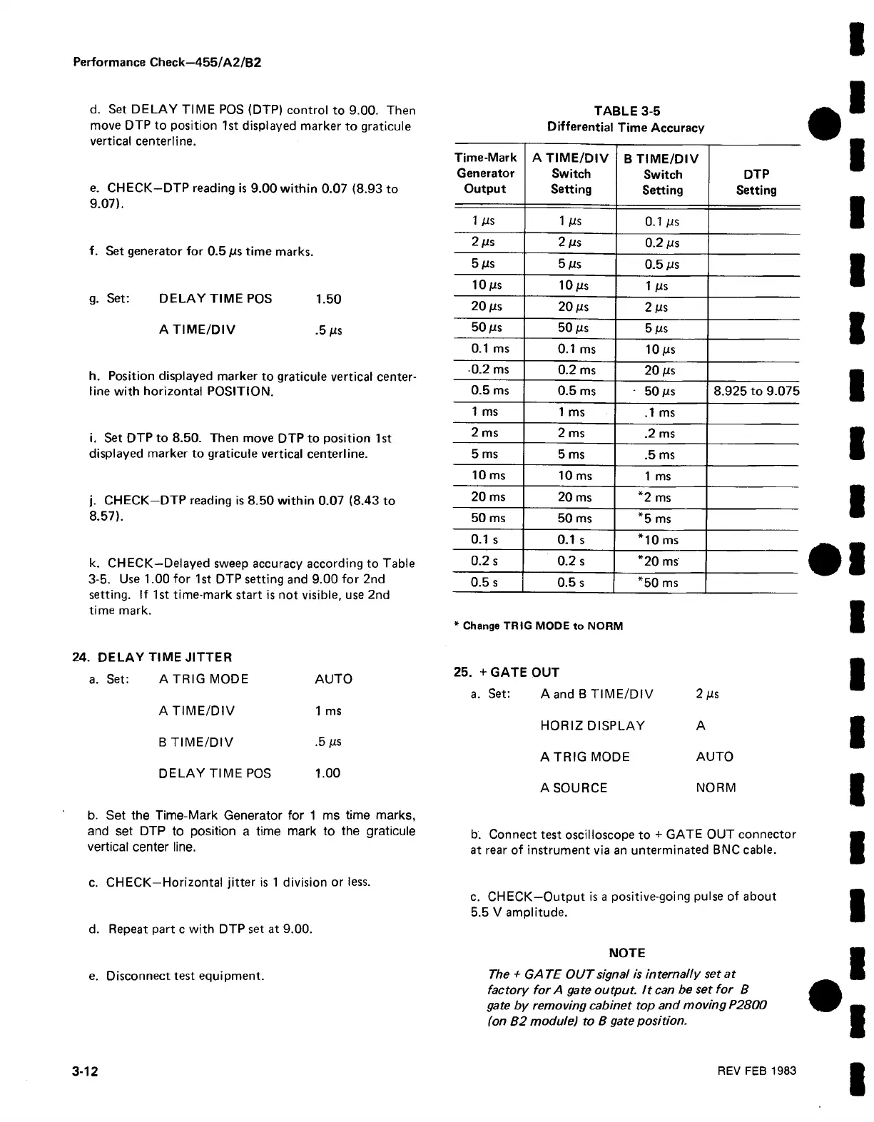
k. CHECK—Delayed sweep accuracy according to Table
3-5. Use 1.00 for 1 st DTP setting and 9.00 for 2nd
setting. If 1st time-mark start is not visible, use 2nd
time mark.
24. DELAY TIME JITTER
a. Set:
ATR IG MODE
AUTO
A TIM E/DIV
1 ms
B TIM E/DIV
.5 ms
DELAY TIME POS 1.00
b. Set the Time-Mark Generator for 1 ms time marks,
and set DTP to position a time mark to the graticule
vertical center line.
c. CHECK—Horizontal jitter is 1 division or less.
d. Repeat part c with DTP set at 9.00.
e. Disconnect test equipment.
TABLE 3-5
Differential Time Accuracy
Time-Mark
Generator
Output
A TIM E/DIV
Switch
Setting
B TIME/DIV
Switch
Setting
DTP
Setting
1 ms
1 Ms
0.1 ms
2 ms
2 Ms 0.2 ms
5 ms
5 Ms
0.5 ms
10 ms
10 ms
1 ms
2 0 ms
20 ms
2 ms
50 ms
50 ms
5 ms
0.1 ms
0.1 ms
1 0 ms
• 0 .2 ms
0.2 ms
20 ms
0 .5 ms
0 .5 ms
50 ms
8 .9 25 to 9.0 7 5
1 ms
1 ms
.1 ms
2 ms
2 ms .2 ms
5 ms
5 ms
.5 ms
10 ms
10 ms
1 ms
20 ms
20 ms *2 ms
50 ms
50 ms
*5 ms
0.1 s
0.1 s
*1 0 ms
0.2 s 0.2 s
*2 0 ms
0.5 s
0.5 s *5 0 ms
* Change TRIG MODE to NORM
25. + GATE OUT
a. Set:
A and B TIME/DIV 2 ms
HORIZ DISPLAY
A
ATRIG MODE AUTO
A SOURCE
NORM
b. Connect test oscilloscope to + GATE OUT connector
at rear of instrument via an unterminated BNC cable.
c. CHECK—Output is a positive-going pulse of about
5.5 V amplitude.
NOTE
The + GA TE OUT signal is internally set at
factory for A gate output, i t can be set for B
gate by removing cabinet top and moving P2800
(on B2 module) to B gate position.
3-12
REV FEB 1983