Circuit Description—455/A2/B2
Pin 9. Free run in. (Used on B sweep only.) Controls
the state of the Sweep Gate output at pin 10. When pin
9 is HI (STARTS AFTER DELAY mode) pin 10 is LO.
When pin 9 is LO, the state of pin 10 is controlled by
the state of pin 12 and/or the Trigger Input signal.
Pin 10. Sweep Gate out. Provides a Sweep Gate output
to trigger the sweep. When pin 10 goes LO the sweep
runs; when it goes HI the sweep is terminated.
Pin 11. Logic Gate out. (Used on A sweep only.) Pro
duces the same output as pin 10, except when pin 9 is
HI (STARTS AFTER DELAY mode). The output at
pin 10 is not affected by the state of pin 9. This logic
gate output is used to initiate the Sweep Control 1C func
tions.
Pin 12. Reset in. The trigger is enabled through this pin.
When pin 12 is LO, pin 10 can be switched from HI to
LO by an adequate trigger signal which starts the sweep.
When pin 12 goes HI, pins 10 and 11 go HI, the sweep is
ended, and the trigger is reset.
Pin 13. Ground pin.
Pin 14. Not connected internally.
Pin 15. +5 volt supply.
Pin 16. Slope in. Connects to the SLOPE switch to
determine the slope (positive-going or negative-going)
from which the trigger signal at pin 2 produces a sweep
gate output.
+5 volts on pin 16 produces a + slope trigger output.
0 volts on pin 16 produces a — slope trigger output.
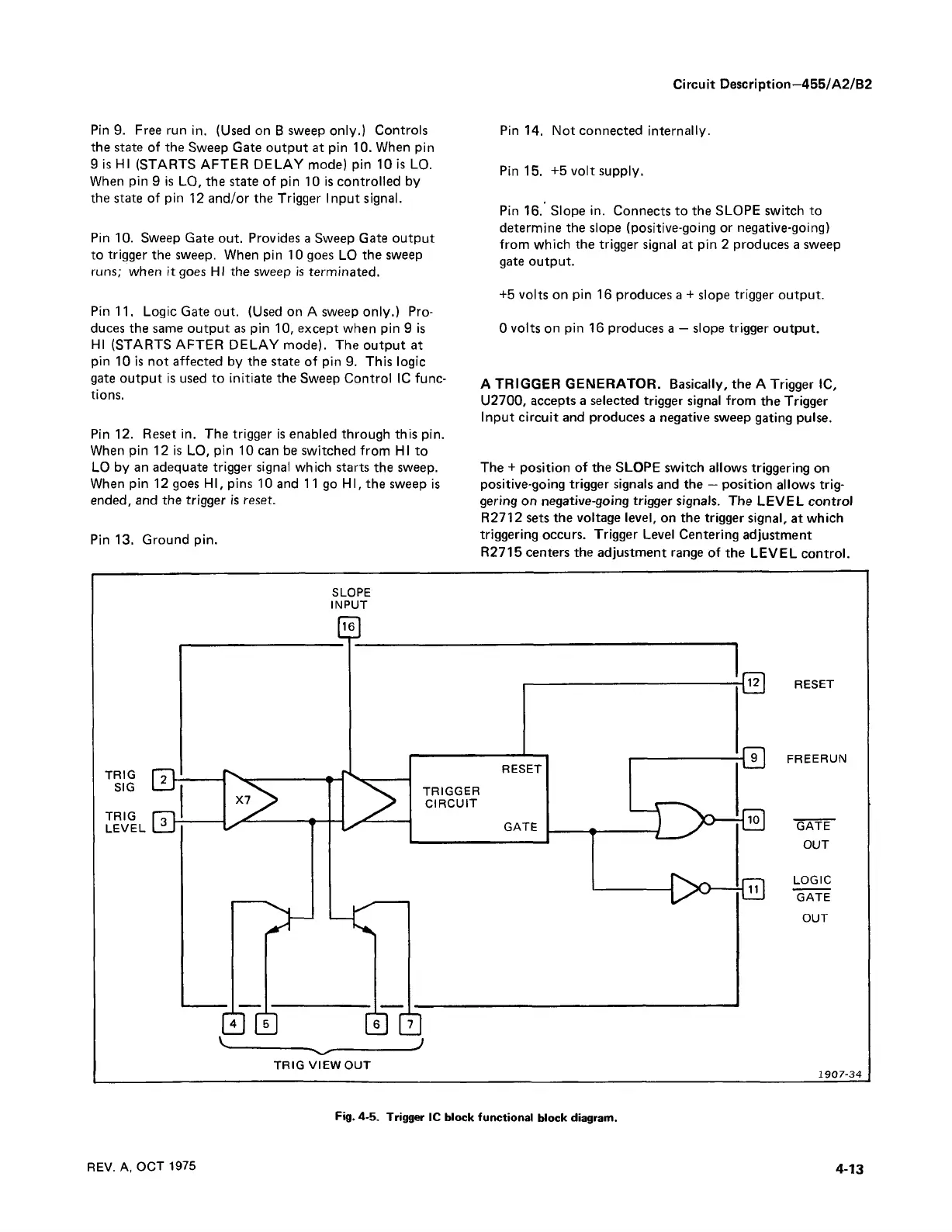
A TRIGGER GENERATOR. Basically, the A Trigger 1C,
U2700, accepts a selected trigger signal from the Trigger
Input circuit and produces a negative sweep gating pulse.
The + position of the SLOPE switch allows triggering on
positive-going trigger signals and the — position allows trig
gering on negative-going trigger signals. The LEVEL control
R2712 sets the voltage level, on the trigger signal, at which
triggering occurs. Trigger Level Centering adjustment
R2715 centers the adjustment range of the LEVEL control.
SLOPE
INPUT
TRIG
SIG
TRIG
LEVEL
TRIG VIEW OUT
RESET
FREERUN
GATE
OUT
LOGIC
GATE
OUT
1907-34
REV. A, OCT 1975
4-13
Fig. 4-5. Trigger 1C block functional block diagram.