Adjustment—455/A2/B2
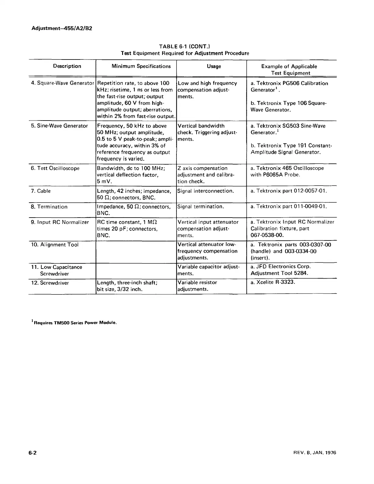
TABLE 6-1 (CONT.)
Test Equipment Required for Adjustment Procedure
Description
Minimum Specifications
Usage
Example of Applicable
Test Equipment
4. Square-Wave Generator
Repetition rate, to above 100
kHz; risetime, 1 ns or less from
the fast-rise output; output
amplitude, 60 V from high-
amplitude output; aberrations,
within 2% from fast-rise output.
Low and high frequency
compensation adjust
ments.
a. Tektronix PG506 Calibration
Generator1.
b. Tektronix Type 106 Square-
Wave Generator.
5. Sine-Wave Generator
Frequency, 50 kHz to above
50 MHz; output amplitude,
0.5 to 5 V peak-to-peak; ampli
tude accuracy, within 3% of
reference frequency as output
frequency is varied.
Vertical bandwidth
check. Triggering adjust
ments.
a. Tektronix SG503 Sine-Wave
Generator.1
b. Tektronix Type 191 Constant-
Amplitude Signal Generator.
6. Test Oscilloscope Bandwidth, dc to 100 MHz;
vertical deflection factor,
5 mV.
Z axis compensation
adjustment and calibra
tion check.
a. Tektronix 465 Oscilloscope
with P6065A Probe.
7. Cable
Length, 42 inches; impedance,
50 £2; connectors, BNC.
Signal interconnection. a. Tektronix part 012-0057-01.
8. Termination
Impedance, 50 £2; connectors,
BNC.
Signal termination.
a. Tektronix part 011-0049-01.
9. Input RC Normalizer
RC time constant, 1 M£2
times 20 pF; connectors,
BNC.
Vertical input attenuator
compensation adjust
ments.
a. Tektronix Input RC Normalizer
Calibration fixture, part
067-0538-00.
10. Alignment Tool
Vertical attenuator low-
frequency compensation
adjustments.
a. Tektronix parts 003-0307-00
(handle) and 003-0334-00
(insert).
11. Low Capacitance
Screwdriver
Variable capacitor adjust
ments.
a. JFD Electronics Corp.
Adjustment Tool 5284.
12. Screwdriver
Length, three-inch shaft;
bit size, 3/32 inch.
Variable resistor
adjustments.
a. Xcelite R-3323.
Requires TM500 Series Power Module.
6-2
REV. B, JAN. 1976