Calibration-PS
501
0
Performance Check Procedure
g.
CHECK-that the current meter changes
=z1
mA while
j.
Repeat the procedure for the NEGATIVE supply. All
changing the line voltage.
specifications remain the same.
h.
Repeat steps a through g for the NEGATIVE supply. All
k. Remove these connections for the next step.
values except for the sign change remain the same.
i.
Remove these connections for the next step.
12.
Check Constant Current
PARD
1
1.
Check Constant Current Load Effect
a.
Turn the PS 501 0 OUTPUT OFF.
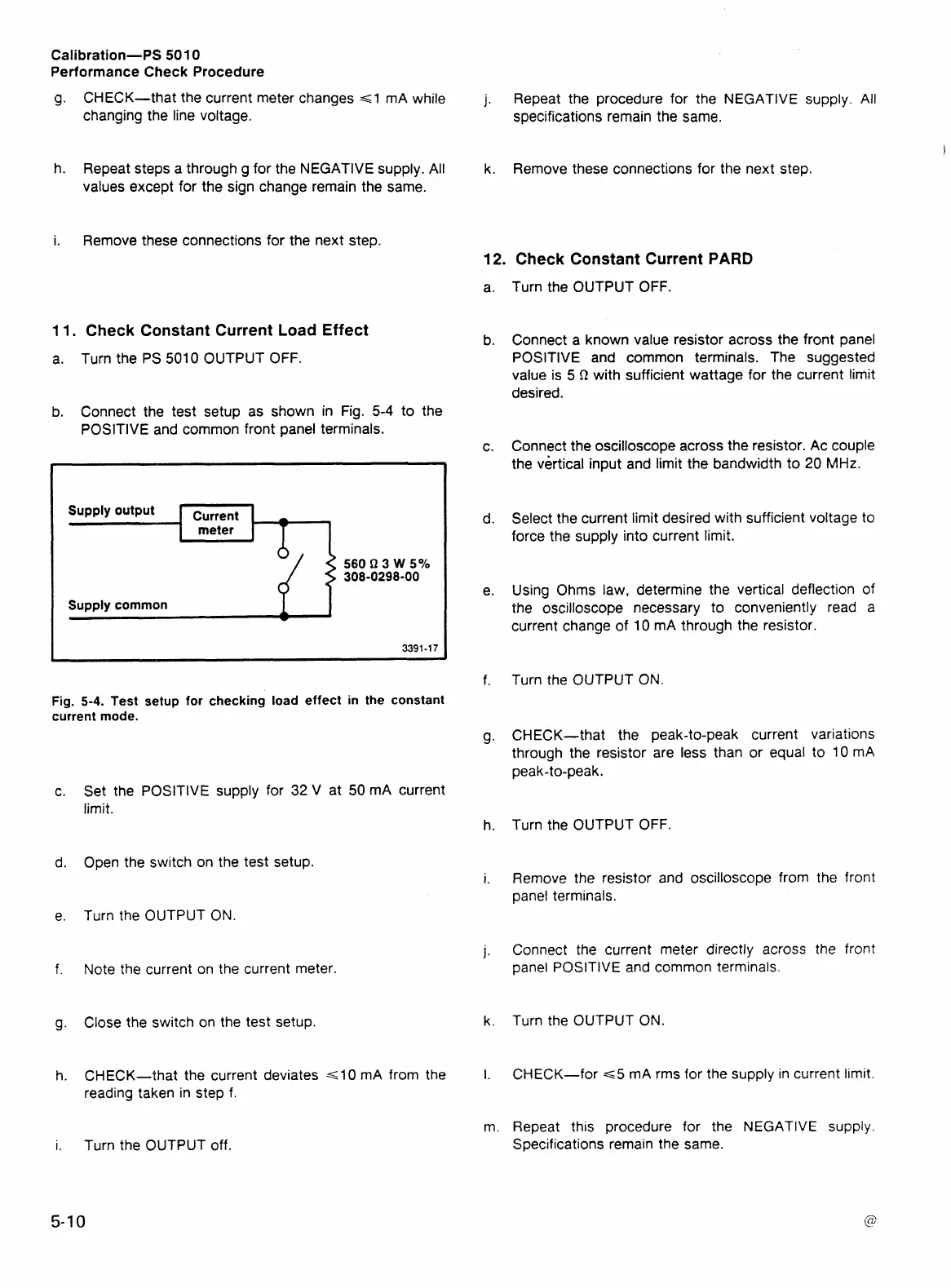
b.
Connect the test setup as shown in Fig. 5-4 to the
POSlTlVE and common front panel terminals.
Fig.
5-4.
Test setup for checking load effect in the constant
current mode.
Set the POSlTlVE supply for
32
V at 50 mA current
limit.
Open the switch on the test setup.
Turn the OUTPUT
ON.
Note the current on the current meter.
Close the switch on the test setup.
CHECK-that the current deviates
~10
mA from the
reading taken in step f.
Turn the OUTPUT off.
Turn the OUTPUT OFF.
Connect a known value resistor across the front panel
POSITIVE
and
common terminals. The suggested
value is 5
Q
with sufficient wattage for the current limit
desired.
Connect the oscilloscope across the resistor. Ac couple
the vertical input and limit the bandwidth to 20
MHz.
Select the current limit desired with sufficient voltage to
force the supply into current limit.
Using Ohms law, determine the vertical deflection of
the oscilloscope necessary to conveniently read a
current change of 10 mA through the resistor.
Turn the OUTPUT
ON.
CHECK-that the peak-to-peak current variations
through the resistor are less than or equal to 10 mA
peak-to-peak.
Turn the OUTPUT OFF.
Remove the resistor and oscilloscope from the front
panel terminals.
Connect the current meter directly across the front
panel POSITIVE and common terminals.
Turn the OUTPUT ON.
CHECK-for
=~5
mA rms for the supply in current limit.
Repeat this procedure for the NEGATIVE
supply.
Specifications remain the same.
 Loading...


