Calibration-PS
501
0
Performance Check Procedure
Sense
23A
I
Output
22A
or
228
DVM
Common
21A
or
218
B
I
Sense common
24A
or
248
1
NOTE
If the Logic Supply fails to meet the
10 mV p-p
PARD specification due to a line frequency compo-
nent superimposed on the output waveform, a
ground loop may exist from the Logic Supply ground
to the oscilloscope through the probe lead. Under
these conditions, to determine PARD, operate the
oscilloscope vertical amplifier in the differential
mode. Set the oscilloscope vertical amplifier for
5
m V/div, ac coupled with a
20
MHz
bandwidth.
k. Remove these connections for the next step.
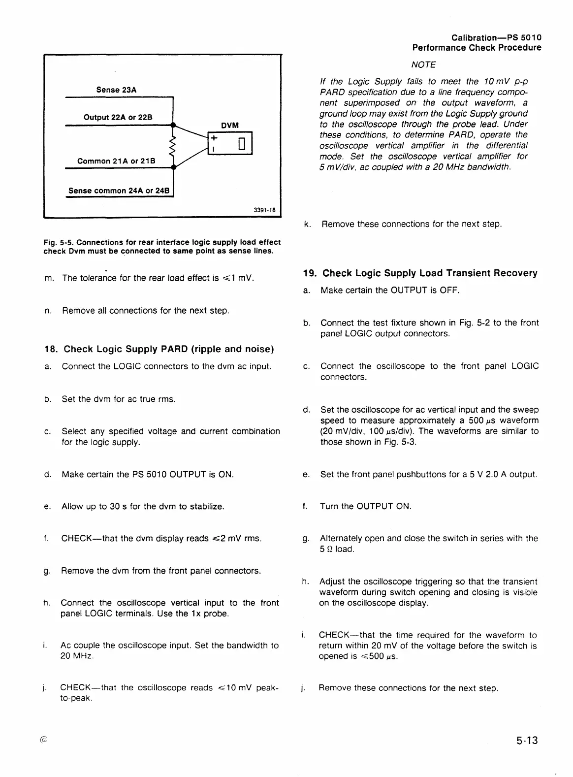
Fig.
5-5.
Connections for rear interface logic supply load effect
check Dvm must be connected to same point as sense lines.
m. The tolerance for the rear load effect is
=GI
mV.
19.
Check Logic
Supply
Load Transient Recovery
a.
Make certain the OUTPUT is
OFF.
n.
Remove all connections for the next step.
18.
Check Logic
Supply
PARD
(ripple
and
noise)
Connect the LOGIC connectors to the dvm ac input.
Set the dvm for ac true rms.
Select any specified voltage and current combination
for
the logic supply.
Make certain the PS
5010
OUTPUT is ON.
Allow up to
30
s for the
dvm
to stabilize.
CHECK-that the dvm display reads
62 mV
rms.
Remove the dvm from the front panel connectors.
Connect the oscilloscope vertical input to the front
panel LOGIC terminals. Use the
1
x probe.
Ac couple the oscilloscope input. Set the bandwidth to
20
MHz.
CHECK-that the oscilloscope reads
G
10
mV peak-
to-peak.
Connect the test fixture shown in Fig.
5-2
to the front
panel LOGIC output connectors.
Connect the oscilloscope to the front panel LOGIC
connectors.
Set the oscilloscope for ac vertical input and the sweep
speed to measure approximately a
500
ps waveform
(20
mVIdiv,
100
psldiv). The waveforms are similar to
those shown in
Fig.
5-3.
Set the front panel pushbuttons for a
5
V
2.0
A output.
Turn the OUTPUT
ON
Alternately open and close the switch in series with the
5
Q
load.
Adjust the oscilloscope triggering so that the transient
waveform during switch opening and closing is visible
on the oscilloscope display.
CHECK-that the time required for the waveform to
return within
20
mV of the voltage before the switch is
opened is
<5OO
j~s.
Remove these connections for the next step.
 Loading...


