Logic
Supply Filter
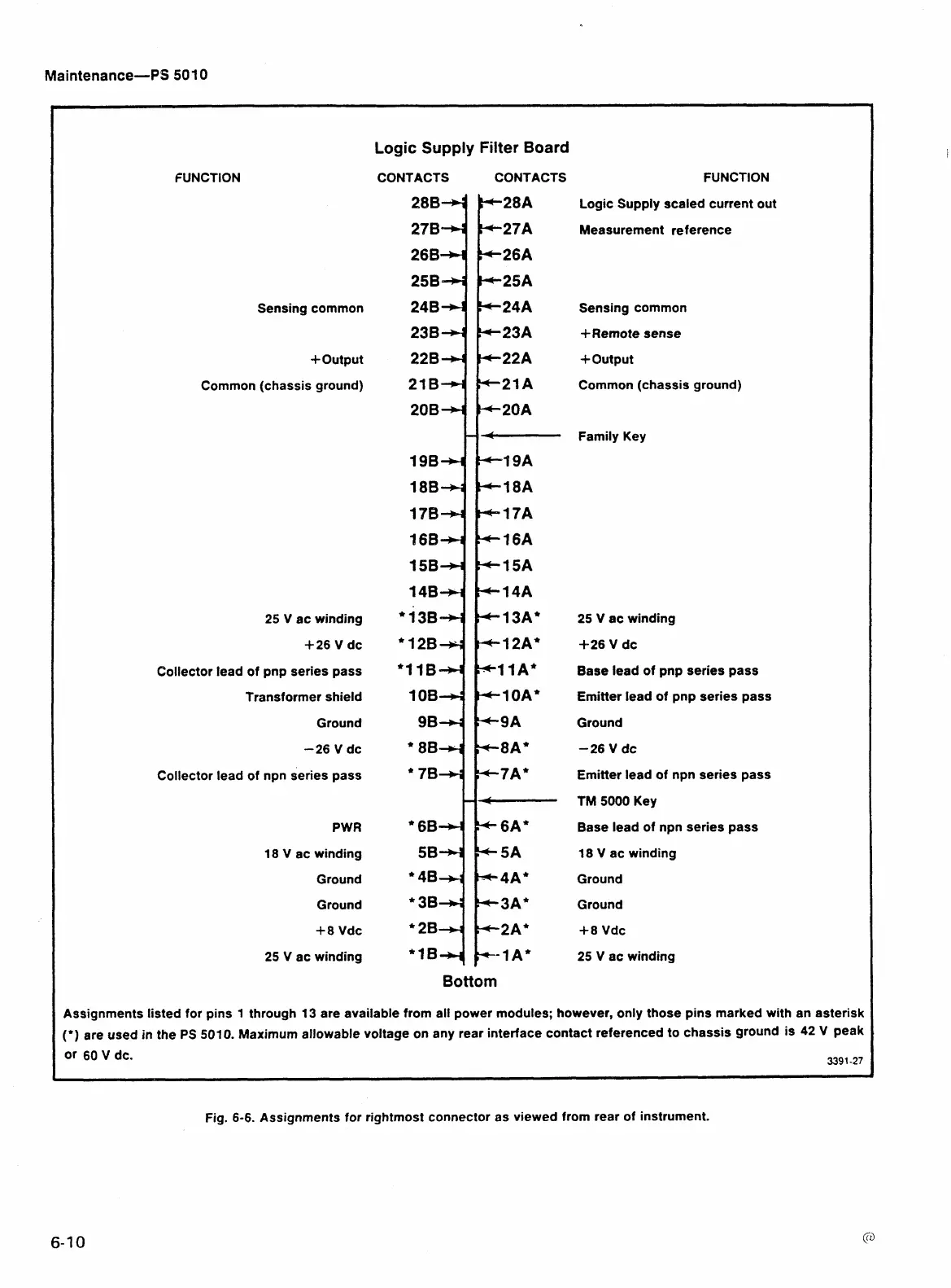
Board
FUNCTION
Sensing common
+Output
Common (chassis ground)
25
V ac winding
+26
V dc
Collector lead of pnp series pass
Transformer shield
Ground
-26
V dc
Collector lead of npn series pass
PWR
18 V ac winding
Ground
Ground
+8
Vdc
25
V
ac winding
CONTACTS CONTACTS
Bottom
FUNCTION
Logic Supply scaled current out
Measurement reference
Sensing common
+Remote sense
+Output
Common (chassis ground
Family Key
25
V ac winding
i-26
V dc
Base lead of pnp series pass
Emitter lead of pnp series pass
Ground
-26
V dc
Emitter lead of npn series pass
TM
5000
Key
Base lead of npn series pass
18 V ac winding
Ground
Ground
+8 Vdc
25
V ac winding
Assignments listed for pins 1 through 13 are available from all power modules; however, only those pins marked with an asterisk
(')
are used in the
PS
5010.
Maximum allowable voltage on any rear interface contact referenced to chassis ground is
42
V
peak
Or
60
V
dc.
3391
-27
Fig.
6-6.
Assignments for rightmost connector as viewed from rear of instrument.